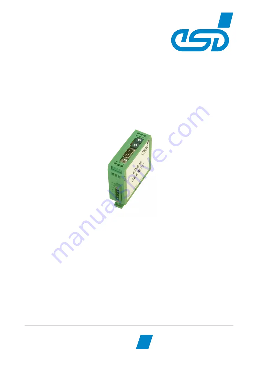
ESD C.2836.03 Hardware Manual Download Page 1

CAN-CBM-Clock                    

Hardware Manual • Doc.-No.: C.2836.21 / Rev. 1.3

Page 1 of 34

                                                  e s d  e le c t ro n ic  s y s te m  d e s ig n  g m b h
                V a h re n w a ld e r S tr. 2 0 7  •  3 0 1 6 5   H a n n o v e r • G e rm a n y
                                                                                h ttp ://w w w .e s d .e u     
P h o n e :  + 4 9  (0 ) 5 1 1  3   7 2  9 8 -0   • F a x :  + 4 9  (0 ) 5 1 1  3  7 2  9 8 -6 8

CAN-CBM-CLOCK

Real Time Clock with CAN Interface

Hardware-Manual

to Product C.2836.03

Summary of Contents for C.2836.03

Page 1: ...s d e le ctron ic sy stem d esig n gm bh V a hre nw a ld er S tr 2 07 30 16 5 H an no ve r G erm an y h ttp w w w e sd e u P h on e 4 9 0 5 11 3 72 98 0 Fa x 4 9 0 5 11 3 72 9 8 6 8 CAN CBM CLOCK Rea...

Page 2: ...entation are reserved by esd Distribution to third parties and reproduction of this document in any form whole or in part are subject to esd s written approval 2016 esd electronics system design gmbh...

Page 3: ...n of facts only Version Chapter Changes versus previous version 1 2 First English version 1 3 Safety Instructions and warning and other messages inserted Classification inserted 1 2 Note on chapter Qu...

Page 4: ...so include a warning relating to property damage DANGER Danger statements indicate a hazardous situation which if not avoided will result in death or serious injury WARNING Warning statements indicate...

Page 5: ...get inside the CAN CBM Clock module Otherwise electric shocks or short circuits may result Protect the CAN CBM Clock module from dust moisture and steam Protect the CAN CBM Clock module from shocks a...

Page 6: ...out by qualified personal It is recommended to send the CAN CBM Clock module to esd for the battery change after 5 years Disposal Devices which have become defective in the long run have to be dispose...

Page 7: ...witch to the CAN Bit Rates 17 3 3 4 Setting the CANopen Node Number 17 3 4 LED Display 18 4 Quick Start 19 5 Connector Assignment 20 5 1 CAN Bus X250 Combicon Style 20 5 1 1 Conductor Connection Condu...

Page 8: ...BM Clock Page 8 of 34 7 CAN Troubleshooting Guide 31 7 1 Termination 31 7 2 Electrical Grounding 32 7 3 Short Circuit in CAN Wiring 32 7 4 CAN_H CAN_L Voltage 32 7 5 CAN Transceiver Resistance Test 33...

Page 9: ...the module is equipped with an internal real time clock RTC The time information of the RTC can be transmitted as time stamp on the CAN bus if the external clock signals fail to appear The time data...

Page 10: ...v 1 3 CAN CBM Clock Page 10 of 34 1 2 View of the Module with Connectors and Coding Switches Figure 2 Position of the connectors and coding switches NOTICE Read chapter Quick Start on page 19 before y...

Page 11: ...nix Contact 5 pin MSTB2 5 5 5 08 CAN net X300 2x3 pin screw connector UEGM 24 V power supply voltage Temperature range 0 50 C ambient temperature Humidity max 90 non condensing Dimensions 25 mm x 87 m...

Page 12: ...Mbit s Table 3 Data of the CAN interface 2 4 Serial Interface Controller MB90F543 Interface RS232 with auxiliary supply DCF77 receiver Connector 9 pin DSUB connector External receiver GPS signal NMEA...

Page 13: ...esd for the battery change after 5 years Frequency tolerance of the RTC maximum at 25 C 20ppm Hold up time Minimum 5 years typical 8 years Battery Type Coin cell 3 V Lithium battery CR1220 Self discha...

Page 14: ...escription of the Units Hardware Manual Doc No C 3010 21 Rev 1 3 CAN CBM Clock Page 14 of 34 3 Description of the Units 3 1 CAN Interface 3 1 1 Interface Circuit Figure 3 Circuit of the CAN interfaces...

Page 15: ...on of the Units CAN CBM Clock Hardware Manual Doc No C 2836 21 Rev 1 3 Page 15 of 34 3 2 Serial Interface 3 2 1 Default Setting of the Module Bit rate 4800 baud Data bits 8 Parity no Stop bits 1 Hands...

Page 16: ...tch Settings Coding switch position when switching on Interpretation by the firmware 0 bit rate will be set 01 7Fh setting of the CANopen node number node ID 80h FEh reserved for future applications F...

Page 17: ...100 8 66 6 9 50 A 33 3 B 20 C 12 5 D 10 E reserved F reserved Table 7 Index of the bit rates 3 3 4 Setting the CANopen Node Number To set the CANopen node number Node ID carry out the steps described...

Page 18: ...or bit rate setting mode is inactive blinking DCF77 Operation LED flashes in the clock pulse of the DCF77 signal short blinking followed by a long off phase incorrect signal short turning off followed...

Page 19: ...l interface 2 Please note that the CAN bus has to be terminated at both ends esd offers special T connectors and termination connectors Additionally the CAN_GND signal has to be connected to earth at...

Page 20: ...crew connection included in the scope of delivery For conductor connection and conductor cross section see page 21 Pin Position Pin Assignment view of socket Pin Signal 1 CAN_GND 2 CAN_L 3 Shield 4 CA...

Page 21: ...2 mm 2 5 mm Conductor cross section stranded min max 0 2 mm 2 5 mm Conductor cross section stranded with ferrule without plastic sleeve min max 0 25 mm 2 5 mm Conductor cross section stranded with fe...

Page 22: ...in Signal 1 n c n c 6 2 RxD Input Vcc_help 7 3 TxD Output n c 8 4 Vcc_help Vcc_out 9 5 GND 9 pin DSUB connector n c not connected Vcc_help 9 V output voltage auxiliary supply for DCF77 receiver e g Ex...

Page 23: ...d to lines with a cross section of up to 2 5 mm Assignment of the screw connectors is the same on both sides of the case They can be used alternatively The center contact is for 24 V and the two outer...

Page 24: ...f the bus However for CAN network design margin must be given for signal loss across the complete system and cabling parasitic loadings network imbalances ground offsets against earth potential and si...

Page 25: ...rop over the wire has to be considered 2 For light industrial environment use at least a two wire CAN cable Connect the two twisted wires to the data signals CAN_H CAN_L and the cable shield to the re...

Page 26: ...n A termination resistor has to be connected at both ends of the CAN bus If an integrated CAN termination resistor which is equipped at the CAN interface at the end of the bus is connected this one ha...

Page 27: ...gnals CAN_H CAN_L and the other two twisted wires to the reference potential CAN_GND and the cable shield to functional earth FE at least at one point 3 The reference potential CAN_GND has to be conne...

Page 28: ...looped through e g DSUB9 connector from ERNI ERBIC CAN BUS MAX order no 154039 The usage of esd s T connector type C 1311 03 is not recommended for single shielded double twisted pair cables because...

Page 29: ...ements defined in ISO11898 2 In addition further recommendations of the CiA like standard values of the cross section depending on the cable length are described in the CiA recommendation CiA 303 1 se...

Page 30: ...S FD P CAN UL CSA 1x 2x 0 25 UL CSA approved Part No 2170272 ConCab GmbH u erer Eichwald 74535 Mainhardt Germany www concab de e g BUS PVC C 1x 2x 0 22 mm Part No 93 022 016 UL appr BUS Schleppflex PU...

Page 31: ...ission line and load impedance are equal these reflections are avoided This test measures the series resistance of the CAN data pair conductors and the attached terminating resistors To test it please...

Page 32: ...ires 7 3 Short Circuit in CAN Wiring A CAN bus might possibly still be able to transmit data if there is a short circuit between CAN_GND and CAN_L but generally the error rate will increase strongly M...

Page 33: ...kage through the CANcircuits please use a resistance measuring device and 1 Switch off the node and disconnect it from the network see figure below 2 Measure the DC resistance between CAN_H and CAN_GN...

Page 34: ...CAN interface ISO 11898 with galvanic isolation up to 1 MB s C 2836 03 Table 10 Order information PDF Manuals Manuals are available in English and usually in German as well For availability of English...

Reviews: