


Power Requirements
|
39
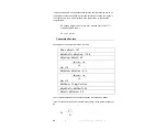
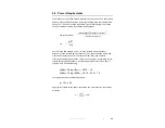
8.0 Power Requirements
The Model 3147 Log Periodic Dipole Antenna may also be used as a transmitting
antenna. Please note the maximum power specification in the specification table
on page 13. The power needed to generate a given field strength in free space
can be estimated according to the transmission equation:
Power transmitted =
(field strength)
2
(distance in meters)
2
(30 x Numeric Gain)
Pt =
|E|
2
R
2
30 g
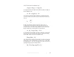
where E is the field strength (in V/m), R is the distance from the transmit
antenna. g is the antenna gain (in linear unit). The power limitation is 80 Watts
maximum continuous power for frequencies below 1 GHz and 40 Watts
maximum continuous power above 1 GHz.. As an example, to generate a 20 V/m
electric field at a given frequency, the measured antenna factor is 23.2 dB(m
-1
).
The gain in dB is computed using:
G(dB) = 20 log
10
(F
MHz
) – 29.79 – AF
G(dB) = 20 log
10
(1000) – 29.79 – 23.2 = 7.0
Converting this value to obtain numeric gain:
g = 10
0.7
= 5.0
Applying the formula for the power transmitted, at 3 m distance from the antenna
boresight,
𝑃
20 3
30 5
24
𝑊
Summary of Contents for ETS-Lindgren 3147
Page 1: ...Model 3147 Log Periodic Dipole Antenna User Manual...
Page 6: ...vi This page intentionally left blank...
Page 9: ...Introduction 9...
Page 10: ...10 Introduction This page intentionally left blank...
Page 12: ...12 Maintenance This page intentionally left blank...
Page 14: ...14 Specifications This page intentionally left blank...
Page 20: ...20 Mounting Instructions This page intentionally left blank...
Page 22: ...22 Operation This page intentionally left blank...
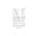
Page 25: ...Typical Data 25 Typical Antenna Factor and Gain for Model 3147...
Page 26: ...26 Typical Data...
Page 29: ...Typical Data 29...
Page 30: ...30 Typical Data...
Page 32: ...32 Typical Data...
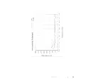
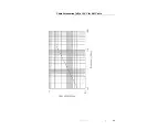
Page 33: ...Typical Data 33 Cable Attenuation dB at 20 C for 6 M Cable...
Page 38: ...38 Radiated Emissions Measurement This page intentionally left blank...
Page 40: ...40 Power Requirements This page intentionally left blank...
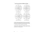
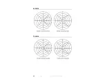
Page 41: ...Typical Antenna Patterns 41 Appendix A Typical Antenna Patterns 400 MHZ 500 MHZ...
Page 42: ...42 Typical Antenna Patterns 600 MHZ 700 MHZ...
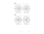
Page 43: ...Typical Antenna Patterns 43 800 MHZ 900 MHZ...
Page 44: ...44 Typical Antenna Patterns 1 0 GHZ 1 5 GHZ...
Page 45: ...Typical Antenna Patterns 45 2 0 GHZ 2 5 GHZ...
Page 46: ...46 Typical Antenna Patterns 3 0 GHZ 3 5 GHZ...
Page 47: ...Typical Antenna Patterns 47 4 0 GHZ 4 5 GHZ...