


17
A. POWER SWITCH
switches unit on when set at „I” position, green LED diode is on (pos. B) which signals
power supply to electric circuits of unit. Cooling fan and pump engine will also be switched on. Green
LED diode on (pos. C) indicates correct liquid circulation in installation. Pump is switched off 5 minutes
after welding process has been stopped. After another 5-minute period cooling fan is switched off and
unit turns into stand-by mode. Yellow LED diode is on at that time (pos. B). After welding process has
been started, fan and pump are activated automatically.
WARNING: If pump emits irregular noises, it signifies presence of air inside. In such a case unit must
be switched off and immediately switched on again.
B. OPERATION INDICATOR
- diode indicating that unit is on (green colour) or in stand-by mode (yellow
colour)
C. COOLING INDICATOR
- diode indicating correct circulation of cooling liquid (green colour)
D. WELDING VOLTAGE REGULATION
is carried out in steps with 5-step switch of coarse regulation and
7-step switch of precise regulation. It means that it is possible to select 35 values of welding voltage.
WARNING: Setting of voltage by means of switches during welding (loaded power source) can cause
damage to unit!
E. OVERHEATING
causes automatic switching off of unit, welding is stopped and it is not possible to
activate welding process with trigger switch on torch. Signal LED diode is on (E). It is possible to continue
welding process after temperature has dropped inside the unit.
F. DIGITAL
METER
indicates actual values of welding current and voltage. Required value is obtained by
setting lever of the switch to a proper position. Semi-automatic welder LKB 400W is manufactured
without meter. Meter is delivered with necessary equipment and assembly instruction KIT (meter has
HOLD function).
G. POTENTIOMETER
to set wire feeding speed (in the range of 1,6
÷
25 m/min)
H. CONNECTION
(Euro connection) to connect welding torch
I. CURRENT SOCKETS
to connect current cable with clamp
J. CONNECTION
PIPE
for cooling liquid outlet (cold liquid)
K. CONNECTION PIPE
for cooling liquid inlet (hot liquid)
L. POTENTIOMETER
of burnback time regulation
M. MODE SELECTOR
2-stroke – motor test – 4-stroke
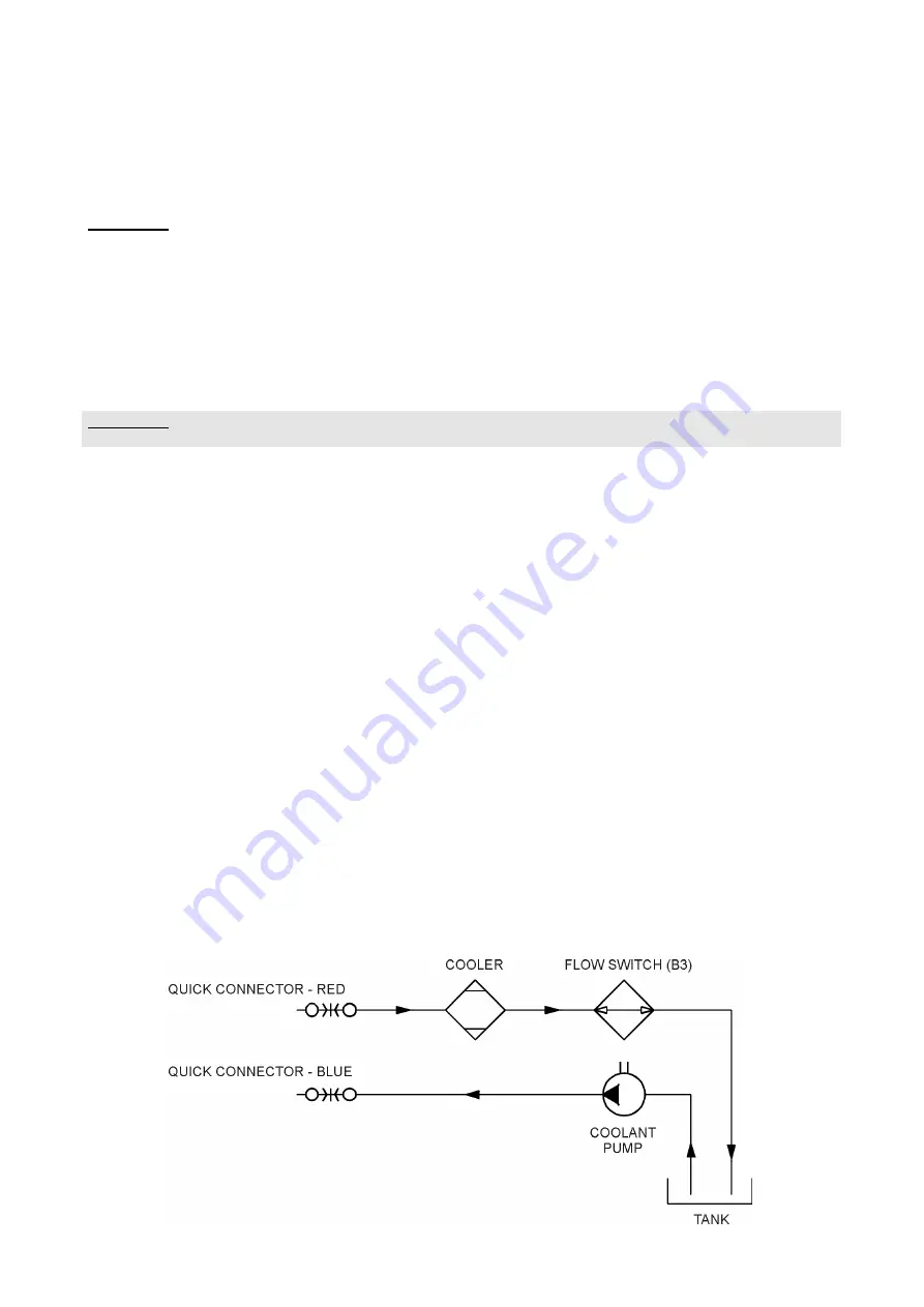
8. COOLING CIRCUIT DIAGRAM
Summary of Contents for LKB 400W
Page 1: ...LKB 400W WELDING RECTIFIER Service manual 0349 300 020 01 01 24 ...
Page 5: ...5 LKB 400W 400V ...
Page 6: ...6 2 COMPONENT POSITIONS CIRCUIT BOARD LA07 A1 ...
Page 7: ...7 DIAGRAM LA07 A1 ...
Page 9: ...9 3 COMPONENT POSITIONS CIRCUIT BOARD LKC31 A2 ...
Page 22: ......
Page 25: ...25 ...


