background image

Chapter 2


HARDWARE INSTALLATION


User's Manual 


8


DC-


DC-


AN


LAN


LAN


LA


LA


COM


COM


rou


rou


2 x 


US


COM


COM


Chapter 2 - Hardware 

Installation


Overview


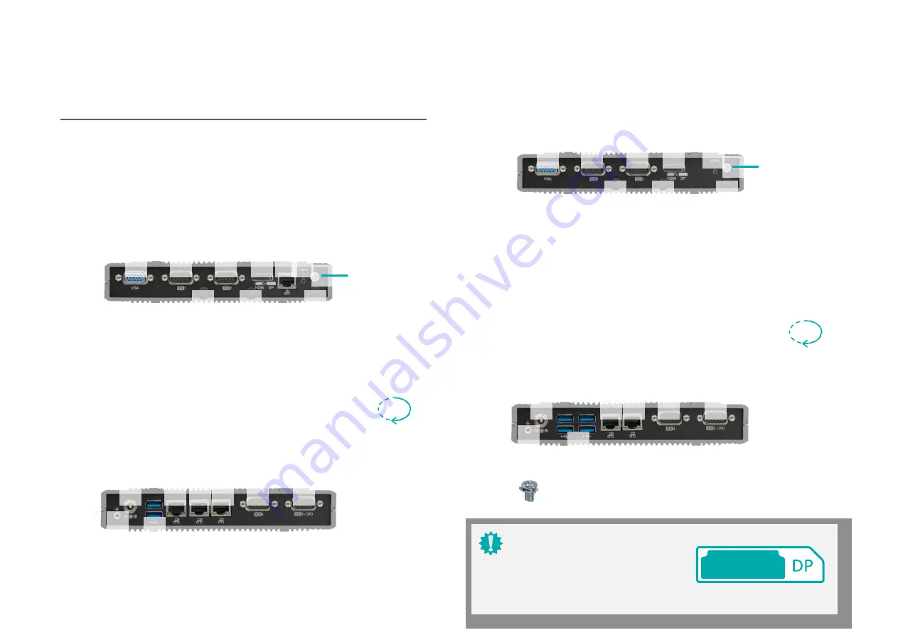
Front Panel (2 x LAN, 4 x USB)


Front Panel (4 x LAN, 2 x 

USB)


VGA/DP


COM 3


COM 4 HDMI/DP


Power LED & Reset


Power Button


LAN 3


VGA/DP


COM 

3


COM 4 HDMI/DP


Power LED & Reset


Power Button


Antenna 

Hole


Antenna 

Hole


Antenna 

Hole


Antenna 

Hole


Antenna 

Hole


Antenna 

Hole


Rear Panel (2 x LAN, 4 x USB)


Rear Panel (4 x LAN, 2 x USB)


1


d  4 x 

3.0


Important:


Please be cautious when inserting an HDMI 

cable into the HDMI/DP port. The HDMI male 

connector shall align to the left of the port as 

illustrated here. The insertion is fairly effortless 

and please reframe from forcing the insertion 

to prevent damage.


HDMI


180°


180°


L


1


d


SB 3.0


Summary of Contents for EW410 7 Series

Page 1: ...EW410xx7 user manual HARDWARE ...

Page 2: ...C Statement on Class B This equipment has been tested and found to comply with the limits for a Class B digital device pursuant to Part 15 of the FCC rules These limits are designed to provide reason able protection against harmful interference when the equipment is operated in a residential installation This equipment generates uses and can radiate radio frequency energy and if not installed and ...

Page 3: ...wer On Select JP7 16 Front Panel JP1 17 COM Serial DIO Switch JP8 JP9 17 SW4 18 I O Ports 19 Graphics Display 19 USB Ports 19 4 x LAN 2 x USB 19 2 x LAN 4 x USB 19 RJ45 LAN Ports 20 COM Serial DIO Port DB9 20 9 36V DC In 21 SATA Serial ATA Connectors 21 Battery 22 Chassis Intrusion 22 Expansion Slots 23 Installing the Mini PCIe Module 23 Installing SIM Card 24 Chapter 3 BIOS Settings 25 Overview 2...

Page 4: ...factory or authorized ser vice agency for all such work 4 We will not be liable for any indirect special incidental or consequential damages to the product that has been modified or altered About the Package The package contains the following items If any of these items are missing or damaged please contact your dealer or sales representative for assistance One System Mini PCIe mounting screws M 2...

Page 5: ...o make sure of proper air ventilation to protect the system from over heating Dress the cables especially the power cord so they will not be stepped on in contact with high temperature surfaces or cause any tripping hazards Do not place anything on top of the power cord Use a power cord that has been ap proved for use with the system and is compliant with the voltage and current ranges required by...

Page 6: ... 64 bit Project support Linux Feature OpenGL 4 2 Direct X 11 1 OpenCL 1 2 OGL ES 3 0 HW Decode H 264 MPEG2 VC1 VP8 H 265 MPEG4 MVC VP9 WMV9 JPEG MJPEG MECHANISM Construction Aluminum Metal Mounting Wall VESA DIN Rail Mount available upon request HW Encode H 264 MPEG4 VP8 H 265 MVC Dimensions 180mm x 33mm x 121 2mm Display 1 x DP HDMI Auto detection 1 x DP VGA W x H x D Weight 700g HDMI resolution ...

Page 7: ...Chapter 1 User s Manual 7 Buttons 1 x Power Button 1 x Reset Button Wi Fi Antenna 3 x Wi Fi Antenna Holes Humidity COMPLIANCE Certification CE FCC class A ...

Page 8: ... COM 4 HDMI DP Power LED Reset Power Button Antenna Hole Antenna Hole Antenna Hole Antenna Hole Antenna Hole Antenna Hole Rear Panel 2 x LAN 4 x USB Rear Panel 4 x LAN 2 x USB 1 G d 4 x 3 0 Important Please be cautious when inserting an HDMI cable into the HDMI DP port The HDMI male connector shall align to the left of the port as illustrated here The insertion is fairly effortless and please refr...

Page 9: ...to desired locations such as walls stands or shelves Locate the mounting holes on the bottom of the system as shown in the photo Screw on the two brackets onto the system with four screws as illustrated below The pre drilled mounting holes on the brackets allow for different wall mount distances The as sembly can either be screwed right onto a wall or hung on steps screws 127 80 108 00 25 00 41 50...

Page 10: ...ed mounting holes 75mm x 75mm 100mm x 100mm to adapt to mounting variants Mount the bracket onto the tapped holes on the back of a monitor a stand or a wall rack Attache the brackets to the bottom side of the system as illustrated below Mount the assembly onto the VESA mount bracket previously attached to the back of a moni tor ...

Page 11: ...f the system opposite to the side where the shorter bracket is mounted The longer bracket shall be on top and overlap with the shorter one on the side 3 Screw the clip onto the side of the assembly When correctly mounted the assembly shall resemble the illustration below 4 Clip the assembly onto a DIN Rail 3 1 1 2 2 Note It does not matter which side of the system the brackets are mounted onto and...

Page 12: ...to four brass stand offs A at four corners An additional screw B located in the vincinity of the CPU shall also be fastened through the board into the top cover to make sure CPU heat is ef ficiently dissipated through the contact with the thermal pad on the inside of the top cover To install the top cover we suggest that the top cover be placed on a work sufrace with the in side facing upward The ...

Page 13: ... Before installing the antenna please make sure that the following safety cautions are well attended 1 Make sure the PC and all other peripheral devices connected to it has been powered down 2 Disconnect all power cords and cables Connect the internal cable to the board s antenna connector screw the antenna connector through the antenna hole on the front panel with washers and nuts and screw on th...

Page 14: ...to the SSD tray while making sure the SATA connector can be access 2 Screw in the four black screws provided in the package to secure the SSD in place 3 Screw in the four black screws provided in the package to secure the SSD in place x3 4 Connect the SATA cable and the SATA power ca ble to the SSD and the board connectors x4 Note After the SATA SSD is correctly mounte please attach the bottom cov...

Page 15: ...aintain contact with the system chassis throughout any procedures requiring ESD protection 2 1 2 6 1 5 Important When the Standby Power LED lights up it indicates that there is power on the system board Power off the PC then unplug the power cord prior to installing any devices Failure to do so will cause severe damage to the motherboard and com ponents 23 eMMC 12 COM4 1 Power Button 24 JP9 13 COM...

Page 16: ...red down 2 Disconnect all power cords and cables 3 Locate the SO DIMM socket on the system board 4 Make sure the notch on memory card is aligned to the key on the socket The system board supports the following memory interface Single Channel SC Data will be accessed in chunks of 64 bits from the memory channels DDR3 SO DIMM Features 2G 4G 8G DDR3L Memory Down One SO DIMM Memory up to 8GB Single Ch...

Page 17: ...sure the retention notch and the clip align as indicated by the dot ted line in the illustration If the retention notch and the clip do not align please remove the card and re insert it Press the card all the way down Step 3 The clips snap automatically and abruptly to the retention notches of the card sounding a distinctive 1 2 On Power On via Power Button default JP7 2 3 On Auto Power On via DC ...

Page 18: ...t is a DB9 connector and can be used as a COM Serial port or a DIO port 8 bit GPIO Both JP8 and JP9 shall be configured concurrently when switching between the two modes Front Panel 10 1 11 2 12 3 10 1 2 6 2 1 1 5 2 6 1 5 10 11 12 10 11 12 10 1 2 3 1 2 3 9 10 1 11 2 12 3 10 1 2 6 2 1 1 5 Pin Assignment Pin Assignment 1 Power Button 2 SUS LED PWR 3 GND 4 SUS LED 5 Reset 6 SATA LED Serial COM Signal...

Page 19: ...failure to start the system due to BIOS mis configuration it is suggested that the system be reconfigured with default values stored in the ROM BIOS To load the default values stored in the ROM BIOS please follow the steps below 1 Power off the system and unplug the power cord 2 Press SW4 for a few seconds 3 Plug the power cord back in and and power on the system 10 1 11 2 12 3 10 1 2 6 2 1 1 5 10...

Page 20: ...tor into the VGA port gen tly tighten the cable screws to hold the connector in place USB allows data exchange between your computer and a wide range of simultaneously acces sible external Plug and Play peripherals The system board is equipped with multiple USB Type A ports at the front panel two USB 3 0 or four USB 3 0 ports along with two internal USB 2 0 pin header ports Wake On USB Keyboard Mo...

Page 21: ...Chapter 2 HARDWARE INSTALLATION User s Manual 21 signals through mSATA ...

Page 22: ... LAN 2 LAN1 COM 4 COM3 or DIO Rear Panel The LAN port allows the system board to connect to a local area network by means of a net work hub BIOS Setting Configure the onboard LAN ports in the Advanced menu ACPI Configuration submenu of the BIOS Refer to the chapter 3 for more information COM 1 COM2 Rear Panel Driver Installation Install the LAN drivers Refer to the chapter 4 for more information F...

Page 23: ... used with modems serial printers remote display terminals and other serial devices Jumper Setting Configure the signal of COM3 DIO port via jumper settings of JP8 and JP9 BIOS Setting Configure the COM ports including its communication mode in the Advanced menu Super IO Configuration submenu of the BIOS Refer to Chapter 3 for more information ...

Page 24: ...TA drives in the Advanced menu SATA Configuration submenu of the BIOS Refer to chapter 3 for more information The 9 36V DC In coaxial supports wide range voltage power connection 1 GN D TX TX GN D RX RX GN D 7 N C GN D GN D 5V SATA 3 0 Pin Assignment SATA Power Pin Assignment 10 1 11 2 12 3 10 1 2 6 2 1 1 5 Important Insufficient power supplied to the system may result in instability or malfunctio...

Page 25: ...sts explosion hazard if the battery is incorrectly installed Replace only with the same or equivalent type recommended by the manufacturer Dispose of used batteries according to local ordinances The board supports the chassis intrusion detection function Connect the chassis intrusion sensor cable from the chassis to this connector When the system s power is on and a chassis intrusion occurred an a...

Page 26: ... PCIe modules that support multiple expansion modules Mini PCIe 1 supports full size Mini PCIe modules for mSATA with SATA or USB 2 0 signals var ies on the stock hardware settings Mini PCIe 2 supports full size Mini PCIe modules for USB2 0 reset signals or nano SIM PCIe signals is also available in the config with 4 LANs installed Nano SIM The Nano SIM socket allows the system to access a subscri...

Page 27: ...d Step 1 Slide the cover to unlock Step 2 Lift the cover Step 2 Press the end of the card far from the socket down until against the stand off Step 3 Screw tight the card onto the stand off with a screw driver and a stand off screw until the gap between the card and the stand off closes up The card should be lying paral lel to the board when it s correctly mounted Step 3 Orient the SIM card and pl...

Page 28: ...ight side of each setup screen The BIOS Setup Utility does not require an operating system to run After you power up the system the BIOS message appears on the screen and the memory count begins After the memory test the message Press DEL to run setup will appear on the screen If the message disappears before you respond restart the system or press the Reset button You may also restart the system ...

Page 29: ...e performance of your system or let you set some features according to your preference X ACPIConfiguration X CPUConfiguration System ACPI Parameters X Audio Configuration X SATA Configuration X PCI Express Configuration X Console Redirection X SIO NUVOTON6116D X LAN Configuration Select Screen Select Item Enter Select Change Opt F1 General Help F2 Previous Values F7 Popup Boot Device List F9 Optim...

Page 30: ...erating system s power management Turbo Mode Enable or disable turbo mode of the processor This field will only be displayed when EIST is enabled C States Enable or disable CPU Power Management It allows CPU to enter C states when it s idle and nothing is executing Thermal Limit Manual Mode Enable this field and manually set a temperature to which the CPU TDP adheres increments from 80 C to 110 C ...

Page 31: ...tion limit Gen1 Gen2 or Gen3 SATA Port 0 Information about the mSATA Mini PCIe 1 device SATA Port 1 Information about the SATA SSD Drive device Port 0 1 and Hot Plug Enable or disable the Serial ATA port and its hot plug function Audio Controller Enable Enable Disable HD Audio Support Select Screen Select Item Enter Select Change Opt F1 General Help F2 Previous Values F7 Popup Boot Device List F9 ...

Page 32: ...ect Item Enter Select Change Opt F1 General Help F2 Previous Values F7 Popup Boot Device List F9 Optimized Defaults F10 Save Exit ESC Exit Console Redirection By enabling Console Redirection of a COM port the sub menu of console redirection settings will become available for configuration as detailed in the following Version 2 18 1263 Copyright C 2020 American Megatrends Inc Aptio Setup Utility Co...

Page 33: ...guration WatchDog Timer Unit Second SuperIO WatchDog Timer 0 Case Open Disabled NCT6116D HW Monitor WatchDog Timer Unit Se lection Select Screen Select Item Enter Select Change Opt F1 General Help F2 Previous Values F9 Optimized Defaults F10 Save Exit ESC Exit WatchDog Timer Unit Select WatchDog Timer Unit Second or Minute SuperIO WatchDog Timer Set SuperIO WatchDog Timer Timeout value The range i...

Page 34: ...040V 1 200V 3 328V 5 016V 12 044 V Temperature CPU o C System o C 37 o C 39 o C Select Screen Select Item Enter Select Change Opt F1 General Help F2 Previous Values F9 Optimized Defaults F10 Save Exit ESC Exit This section displays the system s health information i e voltage readings CPU and system temperature readings Version 2 20 1271 Copyright C 2019 American Megatrends Inc Aptio Setup Utility ...

Page 35: ...upport Set Supervisor Password Set the supervisor password To clear the password input nothing and press enter when a new password is asked Wake On Lan LAN1 LAN2 LAN3 LAN4 Network Stack Ipv4 PXE Support Ipv6 PXE Support Enabled Enabled Enabled Enabled En ab l e or Disab l e Wake on Lan LAN1 MAC Address LAN2 MAC Address LAN3 MAC Address LAN4MACAddress 00 00 00 00 00 00 00 00 00 00 00 00 00 00 00 00...

Page 36: ... TPM 2 0 to achieve hardware level security via cryptographic keys Pending operation To clear the existing TPM encryption select TPM Clear and restart the system This field is not available when Security Device Support is disabled X Boot OS Selection Setup Prompt Timeout NumLock Quiet Boot SCC eMMC Support D28 F0 Windows 10 1 On Disabled Enabled Select the target OS Boot OptionPriorities Boot Opti...

Page 37: ...ted boot device The Boot Override function will only be effective for the current boot The Boot Option Priorities configured in the Boot menu will not be changed X Updating the BIOS To update the BIOS you will need the new BIOS file and a flash utility Please contact technical support or your sales representative for the files and specific instructions about how to update BIOS with the flash utili...

Reviews: