9
User’s Manual – Orion DX 822IR
© 2016 Ernitec. All rights reserved
www.ernitec.com
V 01101116
2.1 P
OWER
C
ONNECTION
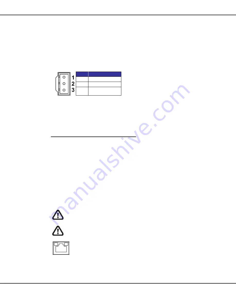
To power up the camera, connect the DC 12V / AC 24V power adaptor to the
power connector of the camera and the power outlet. Refer to the diagram
and pin definition table below for AC 24V power connection.
Pin
Definition
1
AC 24V N
2
GND
3
AC 24V L
Alternatively, users can use an Ethernet cable and connect it to the RJ-45
port of the camera and an IEEE 802.3at (PoE+) 4-Pair 60W switch.
Zero Downtime Power Switching (ZDT)
W
hen users connect DC12V power jack and the RJ-45 port at the same time,
the power input comes from the DC 12V connector. If the DC 12V power
source fails, the camera will switch power input seemly to the RJ-45 port until
the DC 12V power source is restored.
2.2 E
THERNET
C
ABLE
C
ONNECTION
To
connect one end of the Ethernet cable to the RJ-45 connector of the
camera, and plug the other end of the cable to the network switch or PC.
NOTE:
In some cases, Ethernet crossover cable might be needed
when connecting the camera directly to the PC.
NOTE:
Check the status of the link indicator and activity indicator
LEDs. If the LEDs are unlit, please check the LAN connection.
Green Link Light indicates good network connection.
Orange Activity Light flashes for network activity indication.


