background image

7 | Control/operation

Erme AG

38 / 51

Sous vide basins

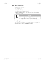
7.6.2.5 Calibrating the unit

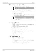
NOTE

• If the unit is calibrated, the manufacturer's calibration is lost.

• Calibrate the unit with the water temperature at 60°C.

If the unit deviates from a high-precision reference thermometer with an accuracy of
maximum ±0.07°C, it can be recalibrated. Calibrate the unit as follows:

1 Call up the "Timer" display mode by pressing the "MODE/ESC" button.

ð

The time currently set is displayed.

2 Press the "

" button four times in quick succession.

ð

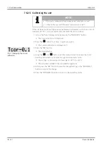
The current calibration is displayed in °C.

Fig. 7: 

Displaying the current

calibration

3 Press the "SET" button.

ð

The display flashes.

4 Using the "

" and "

" buttons, set the desired correction value. Press and

hold one of the buttons to move through the increments faster.

ð

The setting can be selected in the range of -2.0°C to +2.0°C.

ð

The set value is added to the measured temperature.

5 Either press the "SET" button to save the changed setting or the "MODE/ESC"

button to discard the change.

6 Press the "MODE/ESC" button to return to the operating mode.

Summary of Contents for SV1

Page 1: ...Sous vide basins Table models SV1 SV3 SV5 Translation of the original operating instructions Before starting work read these operating instructions ...

Page 2: ... 2018 These operating instructions are protected by copyright and are exclusively for internal purposes Transfer of these operating instructions to third parties their reproduction in any manner and form in full or in part as well as exploitation and or communication of their content without written permission from the manufacturer except for internal purposes is prohibited ...

Page 3: ...neral information 13 2 2 Intended use 13 2 2 1 Foreseeable misuse 13 2 3 Basic safety instructions 14 2 4 Special dangers residual risks 15 2 4 1 Danger due to electrical current 15 2 4 2 Thermal dangers 16 2 5 Emissions 16 2 5 1 Noise emission 16 2 6 The operator s responsibility 17 2 7 Personnel requirements 18 2 7 1 Personnel qualifications 18 2 7 2 Unauthorised personnel 19 2 7 3 Instruction 1...

Page 4: ...tructions 32 7 2 Requirements for the installation site 32 7 3 Switching on the unit 33 7 4 Switching off the unit 33 7 5 Preparing the unit 34 7 6 Operating the controller 35 7 6 1 Display structure 35 7 6 2 Setting parameters 36 7 7 Operating the unit 39 7 7 1 Monitoring the core temperature 39 7 7 2 Carrying out the cooking process 40 7 7 3 Using the timer 41 7 7 4 Controlling the unit remotely...

Page 5: ...enance 48 10 1 Regular maintenance work 48 11 Decommissioning and disposal 49 11 1 Safety instructions 49 11 2 Personnel qualifications 49 11 3 Decommissioning 50 11 3 1 Temporary decommissioning 50 11 3 2 Final decommissioning 50 11 4 Disposal 50 12 Declaration of Conformity 51 ...

Page 6: ...nance and servicing as well as disassembly and disposal Compliance with all specified warning messages and instructions is a prerequisite for safely correctly and efficiently working on and with the unit Observing the above information helps to prevent dangers reduce repair costs and downtimes and increase the reliability and service life of the unit In addition the local accident prevention regul...

Page 7: ... steps are marked by an arrow Example ü Requirement 1 Work step 1 ð Reaction to work step 1 Lists Lists without a mandatory order are displayed as a list with a preceding bullet point Example Item 1 Item 1 sub item A Item 2 Lists with a mandatory order are displayed as a list with a preceding number Example 1 First 2 Second References to chapters pages References to specific chapters in which proc...

Page 8: ... used in these instructions are also provided with pictograms to clarify the type of the possible hazard The following pictograms are used Symbol Meaning General warning message Danger due to electricity Danger due to hot surfaces Observe the instructions General information and helpful tips on handling ...

Page 9: ...ning message of this danger level indicates an impending dangerous situation If the dangerous situation is not prevented it will result in death or severe irreversible injuries Follow the instructions in this warning message to prevent the risk of death or severe personal injuries Risk of injury WARNING Risk of injury Consequences of non compliance Instructions about prevention A warning message o...

Page 10: ...t may result in light or moderate injuries Follow the instructions in this warning message to prevent personal injuries Material damage NOTICE Material damage due to Consequences of non compliance Instructions about prevention A warning message of this danger level indicates possible material damage If the situation is not prevented it may result in material damage Follow the instructions in this ...

Page 11: ...technological state of the art as well as knowledge and experience acquired over many years We reserve the right to make technical modifications in the course of further developing the unit that is the subject of these instructions No claims can be derived from the information figures and descriptions provided in these instructions The manufacturer assumes no liability for damage and malfunctions ...

Page 12: ...ations and wear parts Our General Terms and Conditions apply 1 8 Customer service Please keep the following information readily available for all contact with our customer service department Unit type see type plate on the unit Purchase date see proof of purchase Contact data see Legal notice page 2 NOTE We recommend that the unit s operator conclude a service agreement with ERME AG This ensures t...

Page 13: ...g conditions defined by the manufacturer Any other use beyond this scope is not considered as the intended use The permissible values specified in the Technical data 23 section must be observed This unit is designed to be used in households and other applications for example in kitchens for employees in stores offices and other commercial areas in agricultural companies by customers in hotels mote...

Page 14: ... limb of the user or third parties To life and limb of the maintenance personnel To the unit itself To other equipment Knowledge of the safety and user instructions set out in these instructions provides the basis for safe handling and smooth operation of the unit Set up the unit and its connection lines out of the reach of children Children may not play with the unit Regularly clean the unit Only...

Page 15: ...inspections specified in the instructions Make sure that no liquid runs over the mains connection cable and mains plug Work on electrical equipment must only be carried out by qualified electricians or personnel under the guidance and supervision of a qualified electrician in accordance with electrical engineering regulations Defects identified on the electrical components equipment must be correc...

Page 16: ... is a risk of scalding by hot water or water vapour when the unit is operating Avoid contact with hot water and vapour Make sure the fill level is correct Before draining the liquid let the unit sufficiently cool down 2 5 Emissions 2 5 1 Noise emission Refer to the technical data for the unit s noise emission see Technical data 23 To evaluate the overall noise level at the unit s operating site ob...

Page 17: ... the customer clearly regulate and define the responsibilities for installation operation maintenance and cleaning define the unit operator s responsibility and authorise it to reject instructions from third parties that are detrimental to safety ensure that all personnel who handle the unit have read and understood the instructions In addition it must also train the personnel at regular intervals...

Page 18: ...is her technical training knowledge and experience as well as knowledge of the relevant standards and regulations perform work on electrical units and independently identify and avoid possible hazards The qualified electrician is trained for the particular operation site where he she works and knows the relevant standards and regulations Only persons who can be expected to reliably perform their w...

Page 19: ...ersonnel away from the work area In case of doubt address the personnel and direct them out of the work area Stop working as long as unauthorised personnel are in the work area 2 7 3 Instruction The personnel must be regularly instructed by the operator NOTE For better tracking document the performance of the training programs and have the participants confirm their participation with their signat...

Page 20: ...lating the safety equipment are prohibited The manufacturer no longer assumes any liability or provides any warranty if unauthorised conversions or modifications are made to the unit The electromagnetic behaviour of the unit can be adversely affected by additions or modifications of any kind Therefore do not make any changes or additions to the unit without first consulting the manufacturer and ob...

Page 21: ...y and operating materials can result in damage to and malfunctions or total failure of the unit and endanger safety Only use auxiliary and operating materials that have been specified and approved by the manufacturer The manufacturer assumes no liability for damage resulting from the use of auxiliary and operating materials that have not been approved by the manufacturer ...

Page 22: ...ely shut down the unit 2 Initiate first aid measures 3 Rescue people from the danger zone 4 Notify the responsible personnel at the operation site 5 Alert the emergency services 6 Clear the access roads for the rescue vehicles 2 13 Environmental protection The incorrect handling of environmentally hazardous substances in particular incorrect disposal can cause significant damage to the environment...

Page 23: ...ries 0 7 1 2 1 9 kg Filling quantity 6 14 23 l Power supply 230 Single phase 230 Single phase 230 Single phase V Frequency 50 50 50 Hz Nominal power with heating 1 2 2 0 2 0 kW Mains fuse 13 13 13 A Noise emission 60 60 60 db A Resolution 0 1 0 1 0 1 C Accuracy 0 1 0 1 0 1 C 3 2 Ambient conditions Information Value Unit Operating ambient temperature range 10 30 C Max operating humidity non condens...

Page 24: ...Type plate Fig 1 Type plate The type plate is located on the rear of the unit and contains the following information Manufacturer address CE label Model designation Year of manufacture Maximum filling quantity Mains connection Power Mains fuse Serial no ...

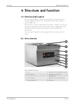
Page 25: ... vacuum bags is set down on a grate and cooked in the water bath in a soft cooker process The core temperature can be monitored during the cooking process using an optionally available food thermometer To protect against damage the unit is equipped with a dry running protection system 4 2 Unit overview 1 2 3 4 5 6 7 8 Fig 2 Front side of the unit 1 Lid 2 Opening for the food thermometer 3 Unit hou...

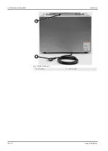
Page 26: ...4 Structure and function Erme AG 26 51 Sous vide basins 9 10 Fig 3 Rear of the unit 9 Chamber 10 Mains plug ...

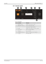
Page 27: ... Function 1 ON OFF button Switches the unit on and off 2 MODE ESC button Selects the display mode Discards the changed settings 3 Display Displays the settings and current values 4 SET button Saves a changed setting 5 button Increases value 6 START STOP button Starts or stops the current function 7 v button Decreases value ...

Page 28: ...s are available for the unit 1 Food thermometer for measuring the temperature inside the food core temperature Sealing pads for sealing the puncture area on the vacuum bag when using the food thermometer Separating grid for separating food with a different cooking time Bag weight to prevent vacuum bags with low weight from floating Steam balls for reducing the heat and evaporation loss when using ...

Page 29: ...mbols and instructions on the packaging Do not remove the packaging until shortly before installation 5 2 Personnel qualifications Transport packaging and storage may only be carried out by personnel who are authorised to do so due to their training and qualifications are tasked to do so by the unit s operator 5 3 Transport inspection On receipt of the unit 1 Refer to the order papers for the scop...

Page 30: ...trical current There is a risk of death when making contact with lines or components that carry current Work on electrical equipment must only be carried out by qualified electricians or personnel under the guidance and supervision of a qualified electrician in accordance with electrical engineering regulations ...

Page 31: ...s customer service department or a similar qualified person to prevent hazards The connection cable must not be tightly stretched kinked crushed or knotted or come into contact with hot surfaces The electrical safety of the unit is only ensured if it is connected to a protective conductor system that has been installed in accordance with the applicable regulations Operating the unit from a socket ...

Page 32: ...quirements for the installation site The following requirements for the installation site must be met in order to ensure safe and smooth unit operation Operate the unit on a firm level and horizontal surface The clearance to the walls and other objects must be at least 30 cm The power socket must be easily accessible so that the mains connection can be quickly disconnected The unit must not be ope...

Page 33: ...pressing the ON OFF button ð ERME appears on the display for approximately 3 seconds Afterwards the current water temperature is displayed 7 4 Switching off the unit Proceed as follows to switch off the unit 1 Press the ON OFF button and hold it for approximately 1 second NOTE The unit switches off automatically after 30 minutes of idle time ...

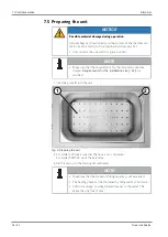
Page 34: ...nts for the installation site see chapter Requirements for the installation site 32 are satisfied 1 Inset the grate 1 into the unit 1 2 Fig 5 Preparing the unit 2 For model SV1 make sure that the hose is not connected For model SV3 SV5 close the ball valve 3 Fill the unit up to the marking 2 with water NOTE Make sure that the maximum filling capacity is not exceeded The heating phase can be shorte...

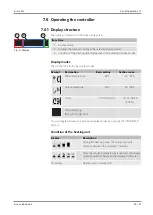
Page 35: ...llowing display modes Symbol Designation Basic setting Setting range Water temperature 65 C 40 95 C Core temperature 50 C 40 95 C Timer 01 00 hh mm 00 01 99 59 hh mm Pump emptying Not with model SV1 You can toggle between the individual display modes by pressing the MODE ESC button Condition of the heating unit Display Description During the heating phase the display cyclically switches between th...

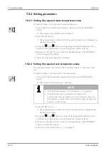
Page 36: ...temperature value The core temperature is monitored if the food thermometer is connected to the unit Proceed as follows to set the desired core temperature 1 Call up the Core temperature display mode by pressing the MODE ESC button ð The current core temperature is displayed NOTE If the food thermometer is not connected is displayed If the thermometer is inserted the unit detects this automaticall...

Page 37: ...E ESC button to discard the change ð The time currently set is displayed ð If the SET button has been pressed the timer starts and the colon flashes ð If the entry has been cancelled with the MODE ESC button or no time has been set yet the timer is not active and the colon does not flash 7 6 2 4 Circulation pump With units fitted with a circulation pump the pump can be activated to completely drai...

Page 38: ...ð The time currently set is displayed 2 Press the button four times in quick succession ð The current calibration is displayed in C Fig 7 Displaying the current calibration 3 Press the SET button ð The display flashes 4 Using the and buttons set the desired correction value Press and hold one of the buttons to move through the increments faster ð The setting can be selected in the range of 2 0 C t...

Page 39: ...f the food thermometer is in the middle of the food NOTE Measure products with different thicknesses at the thickest area Make sure that the vacuum bag is not penetrated on the other side Insert the food thermometer at an angle if necessary Fig 8 Food thermometer connection 3 Connect the food thermometer to the unit 4 Set the desired required value for the core temperature see Setting the required...

Page 40: ...nsert the separating grid as needed 5 Insert the food into the chamber 6 If necessary clamp a bag weight on the vacuum bag to prevent it from floating Fig 9 Cut out in the lid 7 Close the unit with the lid When using the food thermometer make sure that the thermometer connection cable is routed through the cut out in the lid 8 Set the water temperature see chapter Setting the required water temper...

Page 41: ...bottom of the chamber is still always hot Let the unit sufficiently cool down 7 7 3 Using the timer 7 7 3 1 Starting the timer 1 Set the time see chapter Setting the timer 37 2 Press the START STOP button to start the timer ð After the set time has expired an acoustic signal is output 3 Press any button to stop the acoustic signal NOTE The timer operates independently of the heating condition 7 7 ...

Page 42: ... unit Model SV1 1 Hold the hose end in a suitable collection container and connect the hose to the unit s hose connection 2 Remove it again after the water in the hose has drained Models with ball valve 3 Hold the hose end in a suitable collection container 4 Open the ball valve 5 After the water is drained activate the pump and completely empty the unit see chapter Circulation pump 37 6 Close the...

Page 43: ...ce with electrical engineering regulations WARNING Risk of scalding There is a risk of scalding due to hot water and water vapour when the unit is operating Avoid contact with hot water and vapour Let hot components cool down before starting work NOTICE Material damage due to incorrect troubleshooting If pending faults are ignored or not correctly rectified it can result in damage to the unit In c...

Page 44: ...ed TempSens display and acoustic signals Water temperature sensor is defective Contact the customer service department of ERME AG OverCur display and acoustic signals for 4 seconds Overcurrent was detected Acknowledge the error message and switch the unit on and off again If the error is still displayed contact the customer service department of ERME AG OverTemp display and acoustic signals Overte...

Page 45: ...vide basins 45 51 8 4 Localising faults Problem Possible causes Remedy Display does not light up Unit is not switched on Switch on the unit Circuit breaker in the power distribution unit has tripped Switch the circuit breaker back on ...

Page 46: ...arting work NOTICE Possible material damage during cleaning Incorrect cleaning can result in material damage to the unit Do not clean the unit with a high pressure or powerful water jet Make sure that no liquids enter into the connection socket for the food thermometer Do not place the unit in water to clean it 9 2 Personnel qualifications The unit may only be cleaned by personnel who have receive...

Page 47: ...n 4 Remove the coarse dirt and then wipe down with neutral food safe cleaning agents and a soft cloth NOTE Do not use aggressive cleaning agents when cleaning the unit If you detect damage notify the responsible personnel Decalcifying the unit If necessary decalcify the chamber To do this use a standard descaling agent After decalcifying clean the chamber thoroughly with clear water ...

Page 48: ...10 Maintenance Erme AG 48 51 Sous vide basins 10 Maintenance 10 1 Regular maintenance work The unit is maintenance free ...

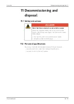
Page 49: ...ng the unit may result in severe injuries or death if the power supply is not switched off or due to stored energies Disconnect the unit from any external power supplies Dissipate any other residual energies 11 2 Personnel qualifications The unit may only be decommissioned and disposed of by personnel who are authorised to do so due to their training and qualifications are tasked to do so by the u...

Page 50: ...ti corrosion agent 11 3 2 Final decommissioning 1 Perform the work steps set out in the Temporary decommissioning section 2 Properly dispose of material components lubricating and auxiliary materials 11 4 Disposal Perform the following steps to ensure proper disposal after disassembly Dispose of the unit according to the local applicable regulations NOTICE Environmental damage due to improper disp...

Page 51: ...tive version 2014 35 EU EMC Directive version 2014 30 EU Applied harmonised standards DIN EN 60335 1 10 2012 Household and similar electrical appliances Safety Part 1 General requirements Authorised representative for the compilation of technical documents ERME AG Technical documentation is available The instructions corresponding to the unit are available In the original version In the national l...

Reviews: