


15
N12- G & HW Series Frequency Controllers 115/230VAC
Setting Instructions
(cont.)
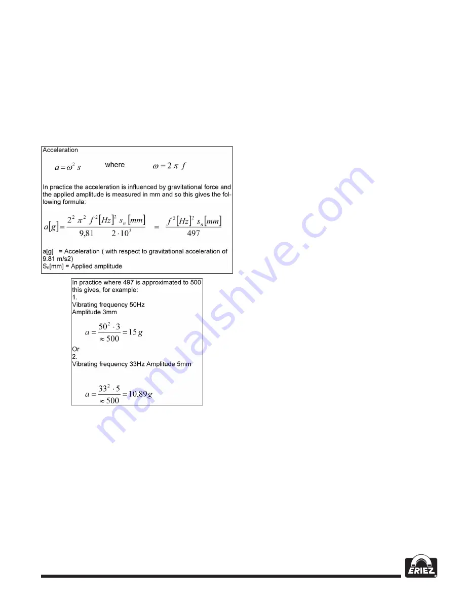
Relationship Between
Acceleration and Amplitude
The sensor measures the momentary acceleration
of the feeder. It generates a sinusoidal output
voltage signal. The acceleration gets higher as the
frequency increases. The sensor signal is greater for
a higher frequency and lower amplitude that for a low
frequency with a higher amplitude.
Using an accelerometer with an output signal of 0.3
V/g the sensor generates a peak voltage of 4..5V for a
peak acceleration of 15g (Example 1), corresponding
to a 3.18.V RMS value.
Example 1:
=> 15 g => 4.,5 V => 3, 18. Veff.
Example 2:
=> 11 g => 3,3 V => 2, 33 Veff.
Because of the vastly different acceleration values of
various feeders, there is a big difference in the feed
back signals, which makes scaling necessary.
Instructions for Setting up the Controller
in Regulation Mode
• Connect control unit.
• Install sensor and connect to controller.
Determining the Resonant Frequency
Manual setting of the vibrating frequency
It is essential that the output frequency is adjusted
with the set point set at a low frequency, otherwise
on hitting the resonant frequency it is possible to
achieve a high amplitude with a low output voltage.
An analog, effective value, current indicating unit
(moving iron meter) must be connected into the
output circuit.
Resonant frequency is reached
when there is a maximum amplitude for a
minimum output current.
Automatic frequency search
• The feeder should be empty for a
frequency search.
• Adjust the set point to zero.
• Select regulation mode (Menu C 008.,
Parameter ACC = I ).
• The optimum frequency of the feeder is found
automatically by initiating the frequency search
(Menu C 008., Parameter A.F.S.). When this has
been found, the controller resets the set point back
to its original value (0).
Optimisating Controller in Regulation Mode
Setting the control range:
1. In Menu C. 096. set parameter P
(Max Limit) to 50%.
2. Set A (Feeder throughput) to 100%.
3. Increase limit P from 50% until the required
maximum feeder throughput is achieved.
The full set point adjustment range of 0…100%
can now be used.
Optimising regulation: For unwanted feeder
oscillation (hunting) or inadequate feedback
regulation for load changes
The response of the regulation circuit can be adjusted
in menu C008. using the parameter PA (Proportional
characteristic or circuit gain) and IA (Integral
characteristic).
In menu C008. reduce PA until the oscillations
are reduced.
Parameter IA should be set to 100 if possible.


