Ericsson PF 768, Troubleshooting Instructions
The Ericsson PF 768 user manual, with troubleshooting instructions, is available for free download on manualshive.com. This comprehensive manual provides all the information needed to operate and troubleshoot the device effectively. Download now to ensure optimal performance of your Ericsson PF 768.
Share
Download


Reviews:
No comments
Related manuals for PF 768

7800
Brand: UniData Communication Systems Pages: 2

SENIOR FLIP XL
Brand: meanIT Pages: 26

17-1165
Brand: Radio Shack Pages: 56

M 16D
Brand: switel Pages: 4

OpenStage M3 Plus
Brand: Unify Pages: 89

i-Style 8.1
Brand: i-mobile Pages: 58
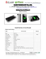
EL-IP4-01
Brand: E-LINK Pages: 4

201512
Brand: Hama Pages: 40

Primo 366
Brand: Doro Pages: 5

Corded IP Phones
Brand: Swissvoice Pages: 12

SP-3003
Brand: Secur Pages: 2

CL 71
Brand: BENQ-SIEMENS Pages: 114

525
Brand: NEC Pages: 187

P400
Brand: Acer Pages: 91

P300
Brand: Acer Pages: 96

V370
Brand: Acer Pages: 51

Liquid Z330
Brand: Acer Pages: 77

Liquid Z2
Brand: Acer Pages: 52


