background image

22

Before drilling any hole, verify that no damage will occur to any
vital part of the  vehicle. Fuel tanks, transmission housings, fuel
lines, brake lines and wiring harnesses are typical items that can
be damaged when a drill bit or screw penetrates through the
mounting surface.

If mounting on a surface covered with carpet, punch holes in the
carpet with a small punch, make a small incision in the carpet,
insert a short piece of metal tubing and then drill through the
tubing. This prevents twisting the carpet with the drill flukes.

4.

Using the six (6) self-tapping screws, secure the mounting bracket
to the mounting surface.

5.

Using the four (4) machine screws and lock washers, secure the
unit to the mounting bracket. It can be fastened in any of three (3)
different positions: parallel to the mounting surface or tilted ±20
degrees from the parallel position. See Figure 4.

Figure 4 - Mounting the Charger

CAUTION

NOTE

7

Moving a few yards in another direction or moving to a higher
elevation may also improve communication.

INTRODUCTION

The Ericsson GE M-RK Standard Vehicular Charger

(344A4616P1) 

and Enhanced Vehicular Charger (344A4616P2) units

can be used with both the M-RK I and M-RK II Personal radios with
swivel  mount or belt clips attached. Any  of the four batteries listed
below can be used with the MR-K I, or II radios and these chargers.

19A149838P1

1200 mAh

19A149838P2

1200 mAh  (intrinsically safe)

344A3278P1

1700 mAh

344A3278P2

1700 mAh  (intrinsically safe)

A vehicular charger enhances the operational versatility of an M-

RK radio in the mobile environment.  See  Table 1 for the  features of
each unit.

The Standard Vehicular Charger (Repeater) (344A4616P1) is

designed to provide recharge of M-RK radio batteries without
provision for operation while in the charger. With this model charger,
M-RK  radio operation is only possible outside of the  charger. The
vehicular repeater is automatically disabled when the M-RK radio is
placed in the Charger and the unit performs the charging function.
The Charger has an ON/OFF repeater enable switch for operation with
the M-RK radio outside the


Charger.  Both fast and slow charge


rates

are built into the charger that operate automatically based upon battery
pack voltage and temperature.

The Enhanced Vehicular Charger (344A4616P2) simultaneously

charges the M-RK's battery pack while allowing the radio to operate as
a mobile radio with an external antenna, speaker, and microphone.
The same fast and slow charge rates are provided (as in Part 1) that
depend upon the battery pack voltage and temperature conditions.
Mobile radio operation is accomplished through the use of an external
speaker, external microphone and  external antenna connections. A
speaker amplifier in the charger unit provides up to 10 watts of audio
output power to an external speaker. A volume control on the charger

Summary of Contents for M-RK 344A4616P1

Page 1: ...U S A LBI 38935 Installation Operator s Manual Mobile Communications STANDARD M RK VEHICULAR CHARGER 344A4616P1 ENHANCED M RK VEHICULAR CHARGER 344A4616P2 ...

Page 2: ...dard Vehicular Charger Repeater Control 344A4616P1 9 Enhanced Vehicular Charger 344A4616P2 10 FRONT PANEL SWITCHES AND INDICATORS 12 Standard Vehicualr Charger 344A4616P1 12 Enhanced Vehicular Charger 344A4616P2 12 BATTERY CHARGER DETAILS 15 INSTALLATION 16 UNPACKING AND CHECKING THE EQUIPMENT 16 PLANNING THE INSTALLATION 17 TOOLS REQUIRED 18 SETTING THE DIP SWITCHES 18 Copyright February 1994 Eri...

Page 3: ...tmospheres Just as it is dangerous to fuel a vehicle with the motor running similar hazards exist when operating a mobile radio be sure to turn the radio off while fueling the vehicle Do not carry containers of fuel in the trunk of the vehicle if the radio is mounted in the trunk 2 Interference to Vehicular Electronics Systems Electronic fuel injection systems electronic anti skid braking systems ...

Page 4: ...oleum LP Gas Powered Vehicles Mobile radio installations in vehicles powered by liquefied petroleum gas with the LP gas container in the trunk or other sealed off space within the interior of the vehicle must conform to the National Fire Protection Association standard NFPA 58 requiring a The space containing the radio equipment shall be isolated by a seal from the space containing the LP gas cont...

Page 5: ...the Federal Communications Commission FCC As an operator of two way radio equipment you must be thoroughly familiar with the rules that apply to your particular type of radio operation Following these rules helps eliminate confusion assures the most efficient use of the existing radio channels and results in a smoothly functioning radio network When using your two way radio remember these rules 1 ...

Page 6: ...tain specific times by means of your call letters Refer to the rules that apply to your particular type of operation for the proper procedure 7 No changes or adjustments shall be made to the equipment except by an authorized or certified electronic technician IMPORTANT OPERATING TIPS The following conditions tend to reduce the effective range of two way radios and should be avoided whenever possib...

Page 7: ...th this model charger M RK radio operation is only possible outside of the charger The vehicular repeater is automatically disabled when the M RK radio is placed in the Charger and the unit performs the charging function The Charger has an ON OFF repeater enable switch for operation with the M RK radio outside the Charger Both fast and slow charge rates are built into the charger that operate auto...

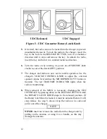
Page 8: ... gives feature comparisons for the two vehicular chargers and Figure 1 shows the Front Panels of both units TABLE 1 FEATURES FEATURE STANDARD ENHANCED Fast Charge Yes Yes Slow Charge Yes Yes Dead Battery Pack Operation No Yes Charge and Ready Indicator Lights Yes Yes Transmitter Enabled Indicator Light No Yes Vehicular Repeater Enabled Indicator Light Yes No 10 Watt External Speaker Amplifier with...

Page 9: ...cular Charger with Repeater 344A4616P1 Operation of the chargers is automatic when the M RK personal radio is inserted The radio is inserted in the charger when the battery needs recharging With the charger standard model no operation of the radio is possible while the radio battery is charging Operation of the radio with this model charger is done after the personal radio battery is charged it is...

Page 10: ...en the repeater is ON 4 After monitoring the channel for activity and finding it free press PTT and make your call Enhanced Vehicular Charger 344A4616P2 The Enhanced Vehicular Charger 344A4616P2 allows the M RK Personal radio to operate in the charger while the battery pack is simultaneously being charged The procedure is as follows 1 Before attempting to insert the M RK personal radio in the char...

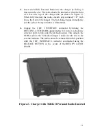
Page 11: ...ly and the yellow charge indicator is illuminated 4 Engage the UDC INTERFACE connector by turning the ROTARY LATCH KNOB approximately 1 4 turn in a clockwise direction until it clicks into the latched position This onnects the M RK radio to the Vehicular Charger s audio circuits and to the external antenna The radio cannot be removed from this position until the UDC INTERFACE connector is unlatche...

Page 12: ...nd radio are now set for mobile operation Use the charger s VOLUME CONTROL KNOB to adjust the external speaker volume level and use the MICROPHONE s PTT button to transmit The red TRANSMIT INDICATOR lights when the radio is transmitting 8 When removal of the M RK is necessary disengage the UDC INTERFACE by pressing down on the RELEASE BUTTON until the ROTARY LATCH KNOB snaps to the released positi...

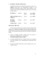
Page 13: ...ut of the charger enables the repeater radio and lights the Amber Indicator light 3 UDC Rotary Latch Knob This knob latches the M RK personal radio in the charger and connects the UDC connector to all circuits within the charger to allow radio operation as a mobile radio It should always be latched when the radio is in the charger and the vehicle is moving Enhanced Vehicular Charger 344A4616P2 Thi...

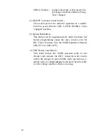
Page 14: ...ushbutton This button can be programmed for many functions but factory programming causes the same action as the M RK Clear function See the M RK Operator s Manual LBI 38732 or LBI 38733 4 UDC Rotary Latch Knob This knob latches the M RK personal radio in the charger and connects the UDC connector to all circuits within the charger to allow M RK radio operation as a mobile radio It should always b...

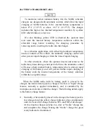
Page 15: ...g In other situations where the operator inserts and removes the radio many times during a short period of time the automatic control will sense a high internal battery temperature due to start up rapid charging of the battery and will prevent further rapid charging of the battery until the internal temperature of the battery stabilizes within the acceptable range When the M RK radio with its batt...

Page 16: ...l engagement of the UDC INTERFACE is not necessary for battery charge operation but is required to operate an M RK Personal in the enhanced vehicular charger during the charging cycle The UDC INTERFACE ROTARY LATCH KNOB should also be in the engaged position whenever the vehicle is moving for both the standard and enhanced models to firmly hold the radio in the charger in case of an accident INSTA...

Page 17: ...passengers in the vehicle in a location that is convenient for the operator to use in a location that allows the operator to easily slip the radio into and out of the unit in a location that allows easy operator access to the external microphone or other options that can be attached Enhanced Vehicular Charger unit only in a location that is protected from water damage in a location that is out of ...

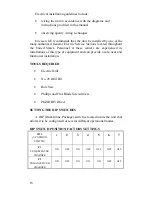
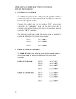
Page 18: ...are experienced in installations of this type of equipment and can provide a safe neat and functional installation TOOLS REQUIRED Electric Drill No 28 Drill Bit Hole Saw Phillips and Flat Blade Screwdrivers POZIDRIV Driver SETTING THE DIP SWITCHES A DIP Dual Inline Package switch is located inside the unit that allows it to be configured for several different operational modes DIP SWITCH POSITION ...

Page 19: ...rear DB 25 connector Pin 10 to the ignition switch Connect this added wire to the ignition ON sense point preferably an accessory point on the fuse panel that is switched on when the ignition switch is in the accessory position and in the RUN position The ignition control logic inside the charger must be enabled by setting the following SW3 dip switch positions SW3 1 Set to OFF SW3 2 Set to ON 2 F...

Page 20: ...n the ignition switch is in the accessory position and in the RUN positions The ignition control logic inside the charger must be enabled by setting the following SW3 dip switch positions SW3 1 Set to ON SW3 6 Set to OFF SW5 1 Set to OFF 2 DISPLAY INVERT CONTROL To M RK II display may either be placed in the normal mode or the inverted mode by setting the following SW3 dip switch positions DISPLAY...

Page 21: ...t to ON MOUNTING THE UNIT The unit can be mounted on the underside of the dash panel of the vehicle or in a DIN size opening in the dash panel It can also be mounted to the vehicle s floor hump using an optional hump mount bracket The following instructions outline the mechanical installation details 1 Select a mounting location Confirm that the location is appropriate as outlined in the section e...

Page 22: ... a small punch make a small incision in the carpet insert a short piece of metal tubing and then drill through the tubing This prevents twisting the carpet with the drill flukes 4 Using the six 6 self tapping screws secure the mounting bracket to the mounting surface 5 Using the four 4 machine screws and lock washers secure the unit to the mounting bracket It can be fastened in any of three 3 diff...

Page 23: ...nnections are used the Charger s DIP switch settings must be changed as shown under SETTING THE DIP SWITCHES to Enable Ignition A If the charger is wired directly to the vehicle s battery it will be necessary to route the power leads through the vehicle s firewall If an existing hole is not conveniently located in the firewall drill a small hole and install an appropriately sized rubber grommet be...

Page 24: ... 19A149590P1 This speaker has a 20 watt rating and a 4 ohm impedance Antenna Connection For P2 Enhanced Vehicular Charger Only The TNC connector at the back of the Enhanced Vehicular Charger must be connected to the external antenna For optimum performance the antenna should be installed in accordance with the installation instructions provided with the antenna package Other Connections See the In...

Page 25: ...25 Figure 5 Interconnection Drawing For P2 Charger Using 344A4616P10 Cable ...

Page 26: ...26 Figure 6 P1 STD Repeater Interconnection Diagram Using 344A4616P12 Cable ...

Page 27: ...27 Figure 7 P2 Enhanced Charger Interconnection Diagram Using Optional ORION Control Head Cable ...

Page 28: ...28 Ericsson GE Mobile Communications Inc Mountain View Road Lynchburg Virginia 24502 Printed in U S A ...

Reviews: