Rotate the encoder C to select slicing mode (SMODE). Available modes for automatic slicing are:
Linear (LIN in the screen on the left) – the sample is sliced in defined number of equally long
slices
Zero Crossing (ZC, for example) – the sample is sliced in defined number of slices, but the slices
are locates as close as possible to zero crossing points. This slicing mode will minimize clicks
when advancing from slice to slice. All trough to get 100% perfect slicing you will need to edit slice
points manually.
SAMPLE DRUM
Start with selecting the envelope RANGE! Rotate the encoder B to choose between SHORT
(max attack, hold and decay time is 1”), MID (max attack, hold and decay time is 3”), LONG
(max attack, hold and decay time is 10”) or RELATIVE. RELATIVE mode is particularly useful
in sample slicing. Attack, Hold and Decay time is automatically defined by sample or slice
length; changing the number of slices will automatically change envelope time. In the RELA-
TIVE mode default setting is 0” Attack, 100% Hold time, and 0” Decay time.
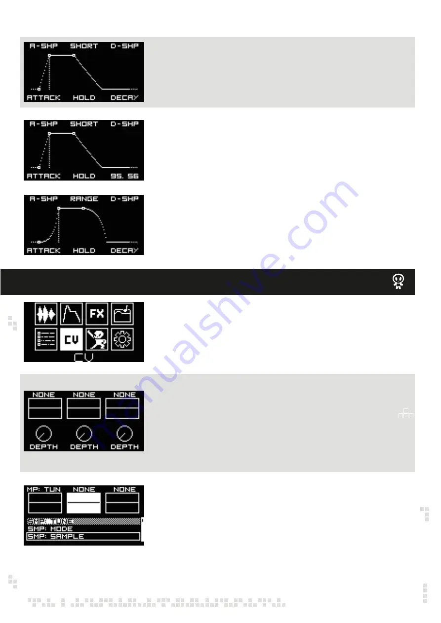
Rotate the encoder A/DATA to adjust the Attack time, the encoder B to adjust the Hold time
and the encoder C to adjust the Decay time. When in loop mode the Decay setting will define
the time in which the loop fades out. In order to have an infinite loop, the Decay time is set to
100 by default, meaning that the sample will play all length.
Rotate the encoder A/DATA to morph the Attack shape from exponential (-50 setting) through
linear (0 setting) to logarithmic (50 setting)
Rotate the encoder C to morph the Decay shape from exponential (-50 setting) through linear
(0 setting) to logarithmic (50 setting).
All envelope settings are saved with the channel instead of individual sample. Please refer to
the PROJECTS menu.
CV ASSIGN MENU – CV MAPPING
Use the encoder A/DATA to navigate to the CV menu and push to confirm.
In the CV menu you can assign each of three CV inputs to different parameters of the Sample
Drum, like tune, play mode, sample select, start, loop and end point, envelope attack, hold
and decay, etc., as well as adjust modulation depth via attenuators.
Rotate the encoder B to assign CV2 input to some of the parameters (SAMPLE SELECT is
selected as the parameter in the example on the left) and push the encoder to confirm. Note
that previously assigned (to CV1) parameters can not be assigned to the next CV input. In the
example on the left TUNE is not available for CV2, because it’s already assigned the CV1.
Same logic is to assign the CV3 to some of parameters using encoder C.
Note, that, if you assign LEVEL to the CV input, you have CV control over the volume of the
sample, basically a VCA.
Now you can use encoders D/BACK, E and F to adjust CV1, CV2 and CV3 respectively levels.
The encoders act as attenuators.


