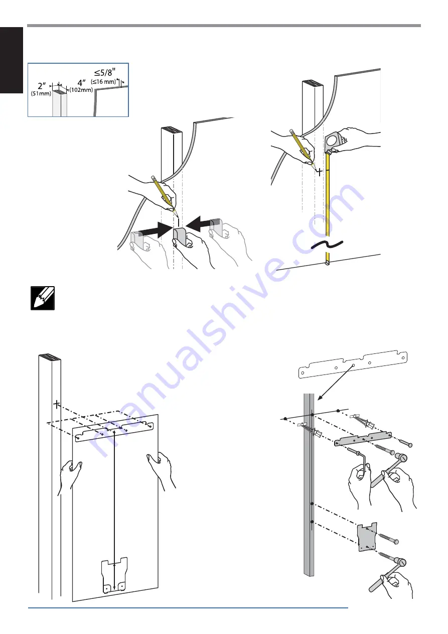
Ergotron Tablet Management Wall Mount 10 Manual Download Page 4

4 of 20

a


b


c


60”-66"

(1524-1676 mm)

2

ENGLISH

888-61-092-G-00 rev. 

D • 08/17 

Hole Option 1


RECOMMENDED

Center Hole in Stud

NOTE: The stud can be located at one of fi ve mounting holes on the top bracket.  While the 
fi rst option (center hole of bracket) is recommended for most cases, you should consult with a 
construction professional to confi rm which method is best suited for your particular situation. 
Options 2-5 are illustrated on the following page in no order of preference.

WOOD AND HOLLOW WALL

Summary of Contents for Tablet Management Wall Mount 10

Page 1: ...O NOT EXCEED MAXIMUM LISTED WEIGHT CAPACITY SERIOUS INJURY OR PROPERTY DAMAGE MAY OCCUR Table of Contents Hazard Symbols Review Safety 2 Components Tools 2 Mounting Considerations 3 Set up 3 8 Wood St...

Page 2: ...s important information that helps you make better use of this product CAUTION A CAUTION indicates either potential damage to hardware or loss of data and tells you how to avoid the problem WARNING AW...

Page 3: ...e Requirements Minimum space needed when removing front cover for service access only If 24 610 mm is not available unit can be removed from the wall for service if needed When mounting to wood stud a...

Page 4: ...d at one of five mounting holes on the top bracket While the first option center hole of bracket is recommended for most cases you should consult with a construction professional to confirm which meth...

Page 5: ...6 mm ENGLISH 888 61 092 G 00 rev D 08 17 STUD LOCATION OPTIONS 2 5 Extreme Left Hole in Stud Middle Left Hole in Stud Middle Right Hole in Stud Extreme Right Hole in Stud Hole Option 2 Hole Option 5 H...

Page 6: ...wall for the anchors Use hollow wall anchors where ever a screw does not get inserted directly into the wood stud Drill the three holes in the top bracket that correspond with the hole option determi...

Page 7: ...stable unsafe condition which could lead to personal injury and or property damage Consult a construction professional if you have any doubt about what this means in regard to your particular situatio...

Page 8: ...4 x 8mm PENTA 2x M4 x 8mm 2x 1x ENGLISH 888 61 092 G 00 rev D 08 17 Place wrench in Cable Restraint and run power cable through as shown NOTE You can push up to 3 feet 1 m of excess power cord up into...

Page 9: ...b c Unplug from wall outlet Remove front cover and save the screws for reattachment Unlock and open door Remove the key to keep door unlocked during service ENGLISH 888 61 092 G 00 rev D 08 17 USB Ca...

Page 10: ...plug through hole in side panel c Open door and pull cable through side panel and secure in the shown cable restraint leaving 4 4 5 102 114 mm of slack d Close door and route cable through cable clips...

Page 11: ...plug through hole in side panel c Open door and pull cable through side panel and secure in the shown cable restraint leaving 4 4 5 102 114 mm of slack d Close door and route cable through cable clips...

Page 12: ...plug through hole in side panel c Open door and pull cable through side panel and secure in the shown cable restraint leaving 4 4 5 102 114 mm of slack d Close door and route cable through cable clips...

Page 13: ...plug through hole in side panel c Open door and pull cable through side panel and secure in the shown cable restraint leaving 4 4 5 102 114 mm of slack d Close door and route cable through cable clip...

Page 14: ...plug through hole in side panel c Open door and pull cable through side panel and secure in the shown cable restraint leaving 4 4 5 102 114 mm of slack d Close door and route cable through cable clip...

Page 15: ...15 of 20 13 14 15 Attach the next set of USB cables to the right side of the unit starting with slot 10 on the USB box When complete reattach front cover Lock doors ENGLISH 888 61 092 G 00 rev D 08 17...

Page 16: ...16 of 20 16 17 18 ENGLISH 888 61 092 G 00 rev D 08 17 NOTE To keep door unlocked pull key out while unlocked NOTE Tablet screen should face the wall when inserting...

Page 17: ...t in the unit LED Indicators To begin charging the tablets plug in the power cord The power cord is used to turn the power on and off Charging occurs whenever the power cord is connected UNLESS a Maci...

Page 18: ...Charging instructions before syncing Devices should be charged at least 50 before starting the syncing process NOTE The devices will not charge while syncing is in process To return to charge mode unp...

Page 19: ...oid overheating Uncoil the cable and do not cover it with any material Do not run cable through doorways holes in ceilings walls or floors Keep this product away from water Do not use it when wet Do n...

Page 20: ...ated weight capacity 24 lb 11 kg Maximum tablet size Individual tablet dimensions including cover up to 10 2 H x 7 9 W x 0 9 D 25 9 x 20 1 x 2 3 cm Individual tablet weight up to 2 4 lb 1 1 kg LED sta...

Reviews: