


PAGE 8
N9A manual v. 2.0
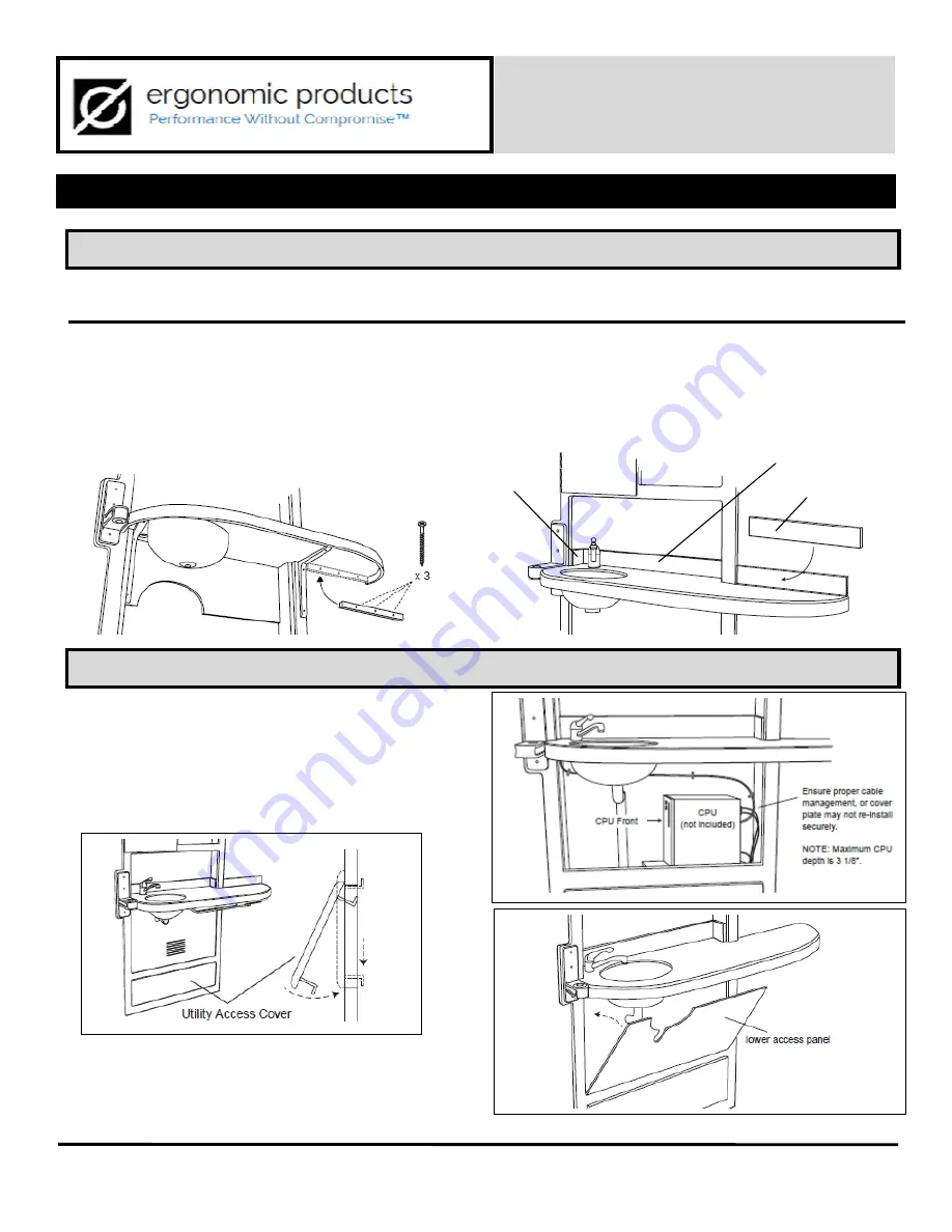
STEP 5 – COMPLETE PLUMBING AND COMPUTER INSTALLATION
STEP 4 – INSTALL SUPPORT CLEAT AND BACKSPLASH
32” INWALL™ COMFORT MEDIA
Model N9A
3 – INSTALLATION cont’d
The extended counter is supported by a 12” x 1” wooden cleat secured directly to the wall beneath the counter
after the main cabinet is secured. The backsplash on this part of the counter is also secured directly to the wall.
1.
Apply silicone to the back of the wooden support cleat.
2.
Press cleat against wall, keeping firm contact with under-
side of extended counter (fig 3.7).
3.
Secure cleat with three supplied #8 x 2-1/2” flat head
screws. Do not overtighten screws; they are simply used to
hold the cleat while the silicone sets.
4. Apply silicone adhesive to the back of each backsplash.
5. Adhere both Side Splash pieces first, Then Adhere the
Back Splash last.
6. Press firmly to wall, butting against faceframe (fig 3.8). Be
sure to position backsplash with indicator arrow UP.
1. To access plumbing stubbing, remove Utility Access
Cover. Slide cover up to clear lower bracket, tilt bottom
towards you and lower cover away from face frame (fig
3.9). (Reverse this process to replace the cover.)
2. Have a licensed tradesman make final plumbing
connections.
3. Position CPU on shelf and run computer and
communications cable as desired (fig. 3.10).
4. Replace lower access panel (fig 3.11).
Ergonomic products • 198 Airport Rd • Fall River, MA 02720 • 866-374-6487
Fig 3.7
Fig 3.8
Fig 3.9
Fig 3.10
Fig 3.11
Side splash
Back splash
Ext ension
Back splash


