


T
he
e
lecTric
M
y
M
ac
P
ro
- Assembly Instructions
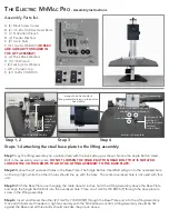
Assembly Parts list
A. (6) Black Screw Covers
B. (2) 1/4-20 x 3.50 Hex Head Bolts
C. (1) 5/32 Allen Wrench
D. (2) Fender Washers
E. (2) Acorn Nuts
F. (3) 1/4-20 x 7/8 BHCS
(THESE 3
ARE ALREADY THREADED IN
THE LIFT ASSEMBLY)
G. (2) Thick Black Washers
H. (1) 7/16 Wrench
I. (2) Locking Star Washers
J. (2)1 x 2 plastic cap
K. (4) 1/4-20 x 3/8 BHCS
Steps 1-4 attaching the steel base plate to the lifting assembly
Step 1:
Lay the lifting assembly on a solid surface with the back side up as shown. Notice the single Button Head
Bolt in the assembly union plate.
DO NOT LOOSEN THE SINGLE BUTTON HEAD BOLT THAT IS NOTATED.
LOOSEN THE 3 OTHER BOLTS TO ADD THE LIFTING ASSEMBLY TO THE BASE PLATE.
Step 2:
Notice the (2) oversized holes in the Base Plate. The Single Button Head Bolt will go into the oversized hole
on the top right, while the other 3 holes should line up with the base. The center oversized hole is not used with this
unit.
Step 3:
With the Base Plate over hanging the table about 2 inches, hold the Lifting Assembly above the Base Plate
and align the Single Button Bolt into the oversized hole. Place one 1/4-20 x 7/8 BHCS{F} through the base plate to
screw in the lifting assembly.
Step 4:
Insert and thread the other (2) 1/4-20 x 7/8 BHCS{F} through the Base Plate and into the Lifting Assembly.
Once all (3) bolts are threaded in, tighten securely with the 5/32 allen wrench{C}. Lifting Assembly should be flat
against the Base and all three bolts should look like the picture above.
Step 1, 2
Step 3
Step 4
not used
bottom of lifting assembly
three button heads that need
screwed in and tightened
oversized hole
matched
up with already
installed
button head
bottom of base plate
A
B
C
D
E
F
G
H
I
J
K
(3) (3)
K
J
lifting
assembly
top of steel base plate
image shows back side of
lifting assembly lining up the button
head bolts
single
button
head
oversized
hole to
match with
button
head
screw
Summary of Contents for The Electric MyMac Pro
Page 1: ...The Electric MyMac Pro...