


SR2 Technical Manual EN
Indice : C
25/03/2019
Firmware v2.9
17 / 31
ERECA SAS - 75 rue d'Orgemont, 95210 St Gratien France
T : +33 1 39 89 76 23 W : www.ereca.fr
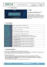
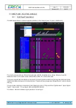
2.4.3 Expansion
The stage racer 2 offers 4x10GB Ethernet expansion channels via the MPO
connector for remote production and future various other applications. As an
example of what can be done:
•
ST2110: Green LED, ON
when ST2110 mode is activated in the machine.
•
ST2022: Green LED, ON
when ST2110 mode is activated in the machine.
•
GIGABIT: Green LED, ON
when extra Gbe ports are transmitted.
•
MADI: Green LED, ON
when extra MADI’s are transmitted on this machine.
•
Link 1-4: Green LED, ON
to indicate which expansion channel is linked with a peer.
2.4.4 Video Status Leds
Genlock I/O
•
IN: Green LED, ON
when the unit is Genlock master on
the network and a valid Genlock signal is detected on the
input.
•
OUT: Green LED, ON
when the unit is Genlock slave on
the network and a valid Genlock signal is detected on the
output.
•
Tri-Level: Green LED, ON
when a Tri-level signal is
detected on the G/L port.
The SDI LED
(1 to 24) section indicates the detection of a video signal and its direction.
•
LED OFF
, when the SDI port is disabled via the web interface.
•
Green LED, ON
when the port is configured as Input and a signal is detected conform to its
standard.
•
Red LED, ON
when the port is configured as Input, but no signal is received or the signal is not
conform to its configured standard. (for example, the port is configured to receive an SD signal but a
3G signal is actually present)
•
Orange LED, ON
when the port is configured as output and a valid signal is routed to that port
•
Red blinking LED, ON
when an input channel is routed to that output port but no signal is detected
2.4.5 Serial and IP
Serial RS
•
RS1 IN, Green LED ON
, when a serial signal is received on the serial port 1
•
RS1 OUT, Green LED ON
, when a serial signal is sent via the serial port 1
•
RS2 IN, Green LED ON
, when a serial signal is received on the serial port 2
•
RS2 OUT, Green LED ON
, when a serial signal is sent via the serial port 2
Ethernet
•
IP1 LINK, Green LED ON,
when an Ethernet link is established on port IP1
•
IP1 1G, Green LED ON,
when the IP link 1 is linked at 1GBps
•
IP2 LINK, Green LED ON,
when an Ethernet link is established on port IP 2
•
IP2 1G, Green LED ON,
when the IP link 2 is linked at 1GBps


