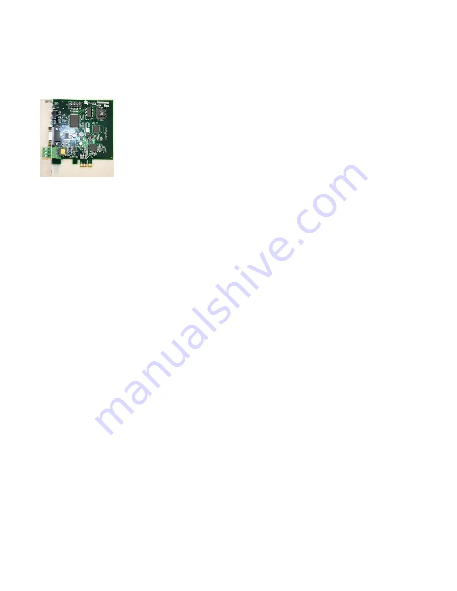
3.0 DLPCIe-Hardware Layout
This Section contains information of the physical position and purpose of the components of the
DLPCIe.
At the top of the bracket has Configure pushbutton
CHA DH+ or DH-485 3 pin Screw terminal (Phoenix Type) pin 1 is the bottom one.
PCI Express Bus connector (CHB the DF1 Physical communication port).
9 Pin DSUB connector (Extra General purpose Serial RS232 communication port).
The LED’s are from top STATUS LED (ERR), NETWORK LED ( CHA) and BUSLED (CHB).
4.0 Mode of Operation
4.1 Online Mode of Operation
Online Mode is the normal operating Mode of the DLPCIe. In this mode the Channels are now
configured as they are defined by the configuration and the DLPCIe Model. The DLPCIe is ready to
interface your equipment.
The Reset pushbutton automatically puts the DLPCIe into Online mode.
4.2 Offline Mode
Once the Configure Pushbutton is pressed the Offline BIOS Manager is started. Using either the
configuration software and the
“DL Offline Manager”
option or a Windows Hyper Terminal type
program with com port settings of 19,2KBaud,8,N,1 and Xon/Xoff flow control.


