background image


13 

Safety Valve 


1.  The 

1 inch return line

 must be connected to the relevant return line port (dumping port) for 

constant oil flow systems, according to the tractor's manual. 

It may not be connected to the 

normal quick couplers of the tractor

. The system is equipped with a 

safety valve of 20 Bar

. If 

the return line is not  coupled and oil pressure exists, the pressure line allows the safety valve  to 

release the oil in order to protect the oil cooler. 


  NB

: With high oil flow rates the oil cooler can still burst. 


2.  The

 ½ inch


pressure line

 is connected to the standard  

  quick couplers. 


3.  Set the oil flow rate at the chosen connector to a ¼ of its  

  capacity 

before

 it can be activated for the first time. 


4.  With the hydraulic pressure line and the return line  

  coupled to the tractor, make sure the lids of the bins  

  and metering units are sealed. 


5.  Activate the tractor control valve to channel oil flow to the fan motor. 


6.  Make adjustments to the oil flow rate to change the air pressure reading to correspond with the 

table in clause 3.3.3. 

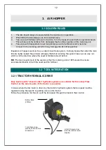
3.2.2  EXTERNAL HYDRAULIC PTO PUMP DRIVE 


Oil Tank 


Pump 


PTO-Gearbox 


Oil Level Indicator 


Filter 


Flow 

Regulating 

Valve 


Summary of Contents for Econo 10000

Page 1: ...OPERATOR MANUAL 3 SECTION MIN TILL AIRSEEDER 4500E 7500E...

Page 2: ...NFIGURATION OF THE DISTRIBUTION SYSTEM 19 4 CALIBRATION 20 4 1 MAINTENANCE AND INSPECTION 21 5 FRAMES 22 5 1 GOLDEN RULES 22 5 2 ADJUSTMENTS 22 5 3 MAINTENANCE AND INSPECTION 23 6 TINE UNITS 24 6 1 GO...

Page 3: ...is missing The location and part number of these decals is identified later in this section of the manual The words Important and Note are not related to personal safety but are used to give addition...

Page 4: ...k TRACTOR OPERATION Be aware of the correct tractor operating procedures when working with implements Review tractor operator s manual Secure hitch pin with a retainer and lock drawbar in centre posit...

Page 5: ...nes Always travel at a safe speed Do Not Exceed 20 m h 32 km h Use an agricultural tractor that is large enough with sufficient braking capacity so that the weight of the loaded equipment towed does n...

Page 6: ...ive connections Ensure all fittings and hoses are in good condition Do not stand under wings MAINTENANCE Shut tractor engine off before making any adjustments or lubricating the machine Block machine...

Page 7: ...7 SAFETY SIGNS...

Page 8: ...8...

Page 9: ...et the draw bars tow eye so that the front and rear shears engage the ground simultaneously Refer to page 22 TINE PRESSURE 3 Set the tine hydraulic pressure to 8 9 MPa NOTE The tine pressure line is l...

Page 10: ...at 180 KPa 7 For a more accurate setting capture the water dispersed by one nozzle over a given distance or time NB The nozzles are spaced at 500 mm the same as a normal sprayer Refer to page 23 2 3 I...

Page 11: ...ht as discussed above giving one the illusion that you are planting too deep WORKING SPEED 3 The speed is determined by the effect of ground dispersion at the back rows on to the front rows Speed can...

Page 12: ...pply that all air entering the system has only one way out which is in the direction where the seed or fertilizer should be fed NB The main requirement of the system is that the metering unit is 100 s...

Page 13: ...ates the oil cooler can still burst 2 The inch pressure line is connected to the standard quick couplers 3 Set the oil flow rate at the chosen connector to a of its capacity before it can be activated...

Page 14: ...1 OPERATION OF THE METERING UNITS The metering unit uses a pintle cog to roll the product from the tank The product falls into the air stream which distributes it through the network of pipes The pin...

Page 15: ...nspect and clean the roller and brush Can be opened at any time even if the bin is full 3 EMPTYING COVER Is removed only to empty the bin NOTE This door may NOT be opened for any reason whatsoever whe...

Page 16: ...nd 4 5 maximum rpm The maximum output input ratio is 1 4 NB No other adjustments may be made to the metering unit as it will influence the settings 3 3 3 ADJUSTMENT OF AIR PRESSURE BY MEANS OF FAN SPE...

Page 17: ...Till air hopper with model numbers specified PRESSURE READINGS ARE SPORADIC Make sure that all pressure gauges are working 100 If the planter is attached directly to the tractor and the pressure jump...

Page 18: ...T STARTS WORKING Once the product enters the airstream the back pressure increases in the system which means that more energy is needed to distribute the product This new pressure reading will stagnat...

Page 19: ...et serves 50mm pipe the rest serves 32mm pipe 2 5 6 7 8 9 10 11 12 2 Outlet Metering unit 4 10 12 14 16 18 20 22 24 4 Outlet Metering unit 8 20 24 28 32 36 40 44 48 6 Outlet Metering unit 12 30 36 42...

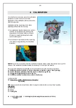
Page 20: ...ZeroMax Gearbox NOTE Count the revolutions that the calibration handle makes while the planter runs over 50 meters The calibration handle rotates theoretically 77 times per 50 meters The required cal...

Page 21: ...WEEKLY Grease all bearings on the drive wheel axles as needed Inspect the drive wheel tyre pressure and set it to 2 Bar 4 1 3 OTHER The filter element in the oil reservoir of the external PTO pump sy...

Page 22: ...take place to prevent undue stress on the cylinders and structure 4 Care must be taken with the speed at which a folded planter is towed As far as possible keep the bins empty when travelling long di...

Page 23: ...rease tandem hinge 5 3 3 WEEKLY 1 Grease wing hinge 2 Check centre wheel pressure 3 Check wing wheel pressure 5 3 4 OTHER 1 Check the gas pressure in the accumulator at your nearest dealer 60 Bar ever...

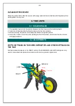
Page 24: ...scribed hydraulic pressure for the tine cylinders 3 When reversing the planter must always be lifted to its highest position 4 Check the V bolts on each tine after planting the first 20 hectares and e...

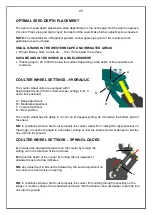
Page 25: ...djustment B Moderate adjustment C Level adjustment D Rest position The coulter wheel has the ability to cut set on its deepest setting 20 mm above the bottom point of the shear NB In conditions where...

Page 26: ...unit to move unconsistently around in the soil NB REDUCE THE SPEED WHILE THE PLANTER MOVES OVER ROCKY AREAS PROCEDURE FOR SETTING THE PRESSURE IN THE ACCUMULATOR Drop the planter s wings into the pla...

Page 27: ...in hinge pin CLEANING PROCEDURE 1 Once the season has ended clean the tine units with soapy water and repair paint scratches with the Equalizer primer followed by the Equalizer top coat 2 Protect the...

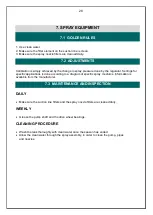
Page 28: ...specific applications is done according to a diagram of specific spray mediums Information is available from the manufacturer 7 3 MAINTENANCE AND INSPECTION DAILY Make sure the suction line filters a...

Page 29: ...R 22 5 4 58 02 MICHELIN RADIAL WING WHEELS 7 50 16 2 8 40 61 TIREPOINT FLOTATION 8 00 15 3 7 53 66 BKT FLOTATION 12 0 18 W11 7 1 102 98 BKT FLOTATION 12 5 80 18 5 9 85 57 BKT FLOTATION 400 60 22 5 4...

Page 30: ...30 9 PROBLEM SOLVING...

Page 31: ...31...

Page 32: ...32...

Page 33: ...33...

Page 34: ...34...

Page 35: ...tener Bolt Size Spanner Size Bolt Torque N m M 6 10 12 M 8 13 25 M 10 17 60 M 12 19 80 M 16 24 200 M 20 30 375 M 24 36 500 M 30 46 1200 For SKF Agri Hub bearings it is recommended that the mounting sc...

Reviews: