EQAS H-5 Series Installation, Operation & Service Manual Download Page 4

 4 


Step 2   

Electrical


• 

IMPORTANT NOTE :  Due to the risk of electrical shock, a licensed electrician experienced in 

spa/baptismal pool heaters should install this unit in strict compliance with the National Elec-

trical Code and any state or local code which may apply.  Units are required to have a 

clearly labeled emergency switch provided by the installer as part of the installation.  The 

switch must be readily accessible to the occupants and shall be installed at least 5 feet 

(1.52 meters) away, adjacent to, and within sight of the unit. 
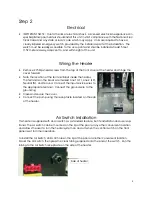
Wiring the Heater 


• 

Remove 2 Phillips head screws from the top of the front cover of the heater and hinge the 

cover forward. 

• 

Note the location of the terminal block inside the heater.  

The terminals on the block are marked Line 1 (L1), Line 2 (L2), 

Neutral (N), and Ground.  Connect the input service wires to 

the appropriate terminal.  Connect the ground wire to the 

ground lug. 

• 

Close and secure the cover.   

• 

Connect the pump using the receptacle located on the side 

of the heater. 

Air Switch Installation 

This heater is supplied with an air switch as a standard feature, but its installation and use is op-

tional.  The air switch can be mounted on the lip of the pool or any other convenient location 

and allows the user to turn the heater system on and off when the control switch on the front 

panel is set for timer operation.   


To install the Air Switch, drill a XX hole on the lip of the pool or another convenient location.  

Mount the Air Switch, then press the clear tubing supplied onto the end of the switch.  Run the 

tubing to the Air Switch receptacle on the side of the heater. 

Side of heater 

Summary of Contents for H-5 Series

Page 1: ...wiring and plumbing of all optional items prior to beginning the installation of this heater HEY The system timer works by moving the minute hand clockwise not turning the body of the timer Turning t...

Page 2: ...d once a month To test the GFIC push the test button The GFIC should interrupt the power Push the reset button and power should be restored If the GFIC does not operate in this manner there may be gro...

Page 3: ...uction fitting and at least 6 below the top of the pool During usage the return fitting must be 3 below the water line to prevent excessive turbulence 2 At this time consider any optional items UV San...

Page 4: ...he heater The terminals on the block are marked Line 1 L1 Line 2 L2 Neutral N and Ground Connect the input service wires to the appropriate terminal Connect the ground wire to the ground lug Close and...

Page 5: ...pool with water The pool is considered full when the water level is 6 below the top of the baptismal 2 Turn the thermostat to the OFF position 3 Set the Timer Mode Switch to the 2 position continuous...

Page 6: ...idered safe for healthy adults only Hotter water increases a risk of hypothermia Young children elderly persons persons having medical problems and persons on medications should have special considera...

Page 7: ...3 88 8 30 2 08 4 15 Nothing Operates Main Breaker Set to on position Sub panel circuit breaker Set to on position GFIC tripped Set to on position Components not plugged in Plug in all components Time...

Page 8: ...later than six months from time of shipment from the FSI factory for the original purchaser repair or at our option re place any defective part If your system is damaged or destroyed by improper maint...

Reviews: