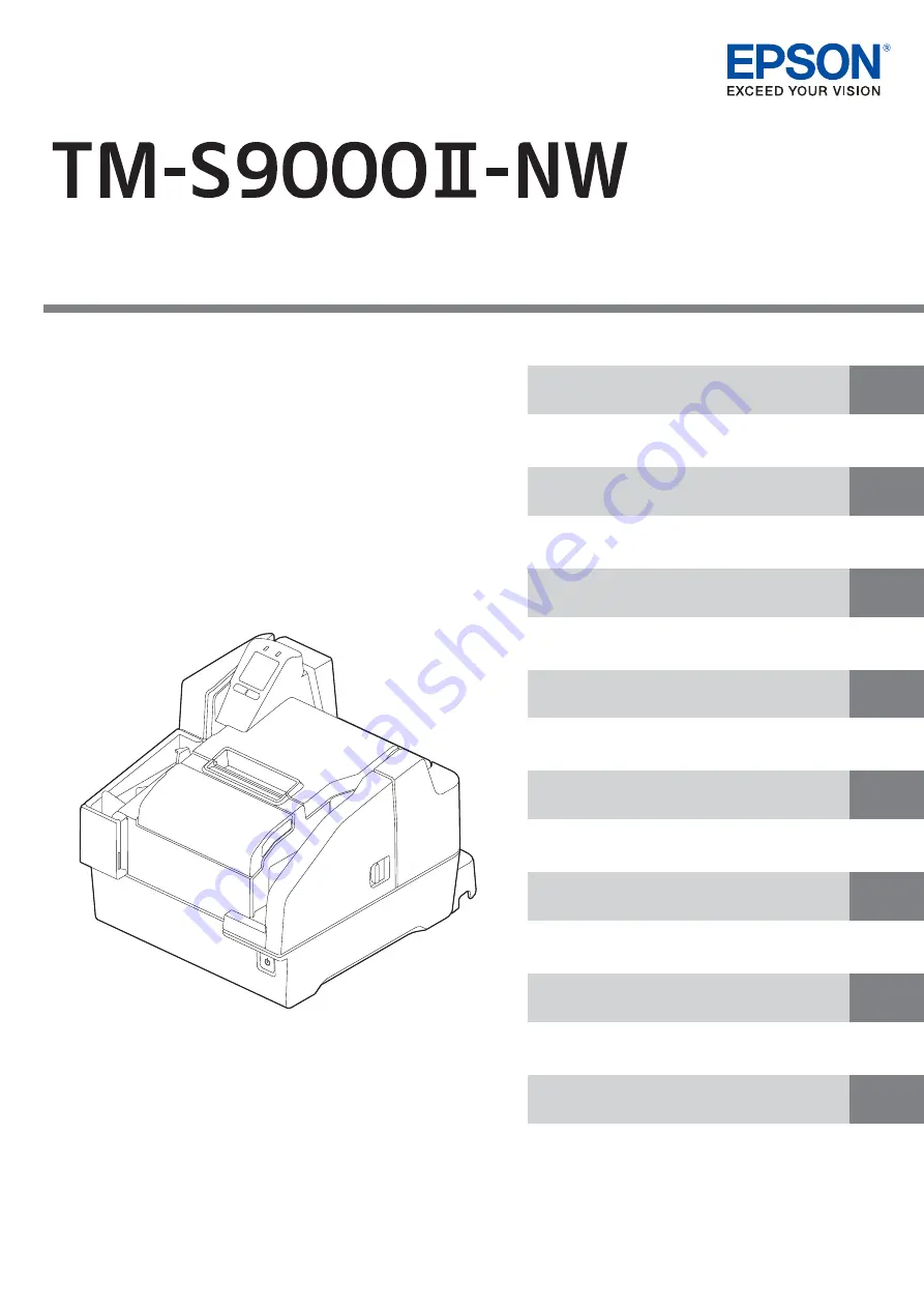
background image

Technical Reference Guide

Handling the Product

Application Development Information

Advanced Product Use

Setup

Product Overview

Safety Precautions

M00151600

Rev. A

Troubleshooting

Product Specifications

Describes precautions that ensure safe use of the 
product. Read this first.

Describes product features.

Describes product and peripheral device 
installation and setup procedures.

Describes advanced product use.

Provides information required for controlling 
this product and application development.

Describes the basic operating procedures of the 
product.

Describes what to do when problems occur.

Provides product specifications, interface 
specifications, and character code tables.

Summary of Contents for TM-S9000II-NW

Page 1: ...afe use of the product Read this first Describes product features Describes product and peripheral device installation and setup procedures Describes advanced product use Provides information required for controlling this product and application development Describes the basic operating procedures of the product Describes what to do when problems occur Provides product specifications interface spe...

Page 2: ...ses incurred by purchaser or third parties as a result of accident mis use or abuse of this product or unauthorized modifications repairs or alterations to this product or excluding the U S failure to strictly comply with Seiko Epson Corporation s operating and maintenance instructions Seiko Epson Corporation shall not be liable for any damages or problems arising from the use of any options or an...

Page 3: ...atures 13 Product Configuration 14 Accessories 14 Part Names and Functions 15 Front 15 Operation Panel 17 Rear 18 Checking the Product Status 20 Replacement Timing of Consumables 20 Statuses and Errors 21 Network Settings Display Mode 25 Cut Sheet Processing Modes 26 High speed Mode 26 Confirmation Mode USB connection only 28 Speed of Each Processing Mode 30 NV Memory 32 NV Graphics Memory 32 NV U...

Page 4: ...SB 44 Attaching the Connector Cover 45 Adjusting LCD Backlight Brightness 46 Checking the Nozzles by Test Printing on Cut Sheets 47 Advanced Product Use 48 Software Settings 48 Function 49 Setting Confirmation Mode 55 Self test Mode 56 NV Graphics Information Print Mode 58 R E Information Print Mode 60 Software Setting Mode 61 Printing a Status Sheet network mode only 62 Initializing Interface Set...

Page 5: ...and Scanner Cover 73 Replacing the Ink Cartridges 74 Replacing Roll Paper 74 Cut Sheet Processing 75 Process Flow 75 Loading Cut Sheets 76 Removing Cut Sheets 77 ID Card Processing 78 Cleaning the Product 79 Cleaning the Exterior 79 Cleaning the Thermal Head and Platen Roller 79 Ink Head Cleaning 80 Cleaning the Paper Feeding Path 80 Cleaning the Scanner 82 Preparing for Transport 83 Troubleshooti...

Page 6: ...pecifications 95 Ink Cartridge 95 Network Interface Specifications 96 USB Interface Specifications 100 USB Type B 100 Printing Specifications 101 Roll Paper Printing 101 Cut Sheet Printing 102 Character Specifications 103 Scanner Specifications 104 Paper Specifications 105 Roll Paper 105 Cut Sheet 106 Printable Area 107 Roll Paper 107 Cut Sheet 108 Roll Paper Print Position and Cut Positions 109 S...

Page 7: ... injury Do not install the product in a location exposed to oily smoke or dust or in a humid location Doing so may cause electric shock or fire Use the product under the environmental conditions specified in the manual Environmental Specifications on page 113 WARNING Do not use other than the specified AC adapter In addition do not use the specified adapter with another device Doing so may cause e...

Page 8: ...oduct immediately if a foreign object or water or other liquid gets inside the product Continued use may cause electric shock or fire Immediately turn off the power and remove the plug from the outlet and then contact qualified service personnel for advice Never disassemble or repair the product by yourself as doing so is dangerous Do not use the product in a location where inflammable gas explosi...

Page 9: ...ts into your mouth immediately spit it out and consult with a doctor There may be some ink around the ink supply port on a removed ink cartridge Take care so that it does not stain the desk or other surface Do not remove the ink cartridge except to replace it Do not open an ink cartridge package until you are ready to install the ink cartridge in the prod uct Do not shake an ink cartridge too hard...

Page 10: ...aution Label The labels affixed to the product indicate the following cautions CAUTION Do not touch the thermal head during or immediately after use They may be very hot after a print operation Thermal head ...

Page 11: ...ld use this product only after giving consideration to including fail safes and redundancies into your design to maintain safety and total system reliability This product in not intended for use in aerospace equipment main communication equipment nuclear power control equipment medical equipment or other applications that require a very high level of reliability and or safety Be sure to check with...

Page 12: ...nance and troubleshooting and the information needed for application development and design Manual Organization This manual is organized as shown below Chapter 1 Product Overview Chapter 2 Setup Chapter 3 Advanced Product Use Chapter 4 Application Development Information Chapter 5 Handling the Product Chapter 6 Troubleshooting Chapter 7 Product Specifications ...

Page 13: ...ted by driver 1 2 LCD for quick and easy understanding of product status and network settings Equipped with High Speed USB USB 2 0 and Ethernet interfaces Wi Fi is also available with the optional OT WL06 Equipped with an interface selection switch physical switch USB connection compatible with the API for TM S9000II MJ Network connection with built in Epson Web API Drawer connection allowed Count...

Page 14: ...ions and accessories for this product depend on the model Accessories Roll paper for initial trial operation Special ink cartridge SJIC18 K x 2 Dedicated AC adapter AC Adapter V USB cable length 170 cm color black AC cable Connector cover Instruction manuals ...

Page 15: ... cut sheets being used 4 Ink cartridge cover Open this cover to install replace the ink cartridge Installing the Ink Cartridges on page 40 Replacing the Ink Cartridges on page 74 5 ASF Auto Sheet Feeder Set checks or cut sheets here to scan them Up to 100 sheets can be set at a time Cut Sheet Processing on page 75 6 ASF guide Pull out the pocket guide to match the length of the cut sheets being us...

Page 16: ...n this cover if cut sheets become jammed Opening the MICR Cover Back Cover and Scanner Cover on page 73 Cut Sheet Jam on page 89 10 Roll paper cover Open this cover to load or replace the roll paper Loading Roll Paper on page 39 Replacing Roll Paper on page 74 11 Manual cutter This cutter is for manually cutting roll paper ...

Page 17: ...les and the product Checking the Product Status on page 20 LCD backlight brightness is adjustable Adjusting LCD Backlight Brightness on page 46 4 Button 1 Left Button 2 Right Each button is assigned the corresponding function that appears at the bottom of the LCD The function on the lower left of the LCD is executed when Button 1 left button is pressed while the function on the lower right is exec...

Page 18: ... Not Come Out 3 Drawer kick connector Connect the drawer cable 4 Wire saddle Pass the USB cable through this saddle to prevent disconnection of the cable 5 Interface selection switch Slide the switch to either left or right to switch between network connection mode and USB connection mode The default position is the left network connection mode Connecting to a Host on page 42 6 DC IN connector Con...

Page 19: ...19 Chapter 1 Product Overview 9 Ethernet connector Connect a LAN cable 10 Status sheet button Press this to print a status sheet Printing a Status Sheet network mode only on page 62 ...

Page 20: ...ning There is not much ink remaining so nearly time to replace the ink cartridge Prepare a new ink cartridge Roll paper is low and the time to replace the roll paper is approaching Pre pare new roll paper Ink cartridge is expended Loading or replacement of the ink cartridge is required Printing on cut sheet is not possible until a new ink cartridge is installed Ink cartridge replacement guidance a...

Page 21: ...LCD on page 85 An ink cartridge is not installed An ink cartridge must be loaded to print on cut sheets There is not enough ink for periodic ink head cleaning The ink cartridge needs to be replaced to perform cleaning LED LCD display Product status POWER ERROR Cut sheets are jammed in the MICR reader Cut Sheet Jam on page 89 Cut sheets are jammed in the back of the product Cut Sheet Jam on page 89...

Page 22: ... error Recoverable Error on page 86 Ink cover is open One or more of the following covers are open MICR cover back cover scanner cover Standing by for insertion of cut sheets Cut sheet detection Card insertion standby Card removal standby LED LCD display Product status POWER ERROR ...

Page 23: ... 39 Ink head cleaning standby Ink Head Cleaning on page 80 Ink head cleaning Thermal head high temperature Ink head high temperature Motor driver high temperature Automatic Recovery Error on page 85 In power on sequence In power off sequence Firmware rewriting data receive in progress Firmware rewriting data writing restoration in progress LED LCD display Product status POWER ERROR ...

Page 24: ...cro execution function operation standby The pump unit is near the end of it s service life Unrecoverable error Unrecoverable Error on page 88 Insufficient ink for periodic ink head cleaning LED LCD display Product status POWER ERROR ...

Page 25: ...er 1 Product Overview Network Settings Display Mode You can display the network settings on the screen by pressing Button 1 and Button 2 at the same time for two seconds Network mode Ethernet Network mode Wi Fi ...

Page 26: ... Criteria When connected over a network When connected via USB Judgment made by Criteria Firmware Overlapping feeding detection result Incorrect insertion detection result Check paper Magnetic waveform detection result External noise detection result Printing result of exceeded media length MICR detection result IQA judgment result Barcode recognition result Judgment made by Criteria Firmware Over...

Page 27: ...ding Ink jet printing Capturing image on both sides Ejection of the cut sheet Fed from the ASF Check for double feeding MICR reading Fed from the ASF Check for double feeding MICR reading Ink jet printing Caputuring image on both sides Ejection of the cut sheet First cut sheet Second cut sheet Third cut sheet ...

Page 28: ...quence The processing sequence changes depending on whether there is overlap operation or not With overlap No overlap Starts send of the next cut sheet after the current cut sheet is fully in the pocket Overlap Starts feeding of the next cut sheet while the current cut sheet is being output to the pocket First cut sheet Fed from the ASF Check for double feeding MICR reading Ink jet printing Captur...

Page 29: ... reading Ink jet printing Capturing image on both sides Stop of paper feeding Ejection of the cut sheet Second cut sheet Third cut sheet Fed from the ASF Check for double feeding Ejection of the cut sheet Fed from the ASF Stop of paper feeding Ejection of the document Waits for a command from the application ...

Page 30: ...twork environment Connection Processing modes Judgment made by Condition details Network connection Web API High speed mode Firmware Operation based on firmware judg ments without instruction from Web applications for high speed processing USB connection PC API High speed mode Firmware Operation based on firmware judg ments without instruction from the host computer for high speed processing Drive...

Page 31: ...he case of a USB connection shown in the following table are the speeds maximum values from the time the first cut sheet is sent out from the ASF to the time the PC application completes receiving the image data of the 100th cut sheet Resolution of captured image 200 dpi grayscale black and white 1 Does not take PC application processing time into consideration Processing mode Media size Color Spe...

Page 32: ... and read as required Memory Switch This switch can be used to configure various product settings For details on memory switches refer to Software Settings on page 48 R E Receipt Enhancement Settings can be configured to have the store logo and other graphics printed automatically at the beginning and the end of receipts For details on R E receipt enhancement refer to R E Information Print Mode on...

Page 33: ...s the number of auto cutter operations product running time and other maintenance counter information in product memory Counter information can be referenced to support periodic inspections consumable replacement and others The head travel distance and the number of auto cutter operations Self test Mode on page 56 ...

Page 34: ...ws the flow of product and its peripheral device setup as shown below 3 Connecting a Power Supply page 38 4 Loading Roll Paper page 39 2 Connecting a Cash Drawer page 36 1 Product Installation page 35 5 Installing the Ink Cartridges page 40 6 Connecting to a Host page 42 7 Attaching the Connector Cover page 45 8 Adjusting LCD Backlight Brightness page 46 9 Checking the Nozzles by Test Printing on ...

Page 35: ...ated power outlet is available In a location with sufficient space around the product to allow for replacement of consumable products and daily cleaning In a location meeting the guaranteed environmental conditions Environmental Specifications on page 113 The packing materials and packaging box are required for future transportation Keep them in a safe place When moving the product lift it up by g...

Page 36: ...rawer kick connector When using a drawer open close signal a switch must be provided between drawer kick connector pins 3 and 6 Load resistance by a drawer kick solenoid or others of at least 24 Ω and input current of no more than 1 A Use of only the 24 V output of drawer kick connector pin 4 for the drawer power supply Drawer Kick Connector Connection Diagram Simultaneous operation of two drives ...

Page 37: ...onnector until you hear it click into place WARNING Use a shielded cable for the drawer cable Be sure to use product power connector pin 4 for drawer power Do not plug a general public phone line or other similar connector to the drawer kick connector Doing so can damage the public phone line or product ...

Page 38: ...tlet with a ground 4 Place the AC adapter with its label facing downward WARNING Use only the specified AC adapter Not doing so may cause a fire or electric shock Electrical Specifications on page 95 Do not plug the AC cable into a power outlet whose voltage does not match the input voltage of the AC adapter Doing so can damage the product If you discover an abnormality immediately turn off the pr...

Page 39: ...oad roll paper making sure it is oriented correctly 3 Pull out the leading edge of the roll paper a little and close the roll paper cover If the product is turned on the roll paper will be cut automatically CAUTION Take care not to press on the manual cutter with your hand or fingers Doing so may cause injury ...

Page 40: ...ow the proce dure in this section 1 Check that the product is powered on Turning the Power On on page 71 2 Open the ink cartridge cover Opening the Ink Cartridge Cover on page 72 3 Remove a new ink cartridge from its bag 4 Peel the yellow film from the ink cartridge CAUTION Read the precautions on handling carefully before installing the ink cartridges Cautions on Ink Cartridges on page 9 CAUTION ...

Page 41: ...flashing to on The installing of ink cartridges is now complete CAUTION Never open any cover of the printer or turn off the printer during ink charging while the POWER LED is flashing Doing so will consume a large amount of ink which may result in the need to replace the ink cartridges before the completion of charging The ink cartridges included in the product package are used for initial chargin...

Page 42: ...ter or hub 3 Turn on the product 4 Press Button 1 and Button 2 at the same time for two seconds to display and check the network settings of the product 5 Start a browser on the host device and enter the IP address of the product to open Web Config 6 Modify the product s network settings in Web Config 7 Restart the product The product is in the network mode by default Network Ethernet ...

Page 43: ...it 4 Turn on the product 5 Press Button 1 and Button 2 at the same time for two seconds to display and check the network settings of the product 6 Start a browser on the host device and enter the IP address of the product to open Web Config 7 Modify the product s wireless network settings in Web Config 8 Disconnect the LAN cable 9 Restart the product The product is in the network mode by default N...

Page 44: ...er to the connector on the back of the product Rear on page 18 The product is in the network mode by default Pass the USB cable through the wire saddle to prevent accidental disconnection Use of the included USB cable is recommended Use of another USB cable can result in improper operation during large volume data processing when scanning a series of docu ments Network USB ...

Page 45: ...45 Chapter 2 Setup Attaching the Connector Cover When using the connector cover attach it as shown in the figure ...

Page 46: ... being used The changed setting is retained even if the power is turned off Available brightness settings are bright normal and dark 1 Open the ink cartridge cover Opening the Ink Cartridge Cover on page 72 2 Press Button 1 dark to make the display dark or Button 2 bright to make the dis play bright 3 Close the ink cartridge cover ...

Page 47: ...lurred it means that ink head cleaning is required Ink Head Cleaning on page 80 Firmware version 1 02 ESC POS Buffer Capacity 4K bytes fixed Handshaking operation busy condition Receive buffer full fixed Automatic line feed CR command function Disabled Resident character Alphanumeric Power on status Disabled Receipt cover open Auto recoverable error Remote wakeup Enabled Nozzle check pattern Maint...

Page 48: ...aper Reduction Print density when multiple tone printing Sets time to check ink head cleaning Print Start Position Validation settings Cut sheet settings Time to enter power saving mode Function to prevent printing on the back side of docu ments endorse without magnetic ink characters MICR appearance judgment position using the func tion to prevent printing on the back side of docu ments endorse w...

Page 49: ... Selectable level 1 to 13 70 to 130 Default setting Level 7 standard In order to ensure high print quality setting the print density is recommended in accordance with the type of paper being used as shown in the table below Paper autocutting after closing the roll paper cover Cut default setting No cut not recommended Original paper type Density AF50KS E 4 85 TF50KS EY P220AGB 1 5 90 TF60KS E PD16...

Page 50: ...s not reduce default setting 25 50 75 Bar code height reduction rate Does not reduce default setting 25 50 75 Print density when multiple tone printing Selectable level 1 to 13 70 to 130 Default setting Level 7 In order to ensure high print quality setting the print density is recommended in accordance with the type of paper being used Sets time to check ink head cleaning Time hh mm can be specifi...

Page 51: ...ation settings Top margin default setting 0 and left margin default setting 0 settings are configurable Paper feed direction 5 to 10 mm Default setting 5 mm origin Paper feed direction Top margin dots Left margin dots Allowable printing area 50 8 mm 18 mm 10 mm ...

Page 52: ...ower saving mode This time can be set within the range of 100 ms 0 1 second to 3600 s 60 minutes Default setting 300 s 5 minutes Function to prevent printing on the back side of documents endorse with out magnetic ink characters Disabled default setting Enabled Paper feed direction Top margin dots Left margin dots Allowable printing area 50 8 mm 18 mm 10 mm ...

Page 53: ...an be specified in 0 1 mm units Settings for auto Top Logo Bottom Logo printing Key codes You can select from among the key codes of pre registered logos Alignment Align left Align center Align right Paper length 160 mm MICR line detection position 0 1 mm units MICR character start position 50 8 mm 18 mm 10 mm Paper feed direction ...

Page 54: ...go Bottom Logo printing Top Logo printing when feeding is up to the cut position Disabled Enabled default setting Top Logo printing when the product is turned on Disabled default setting Enabled Top Logo printing when covers are closed Disabled Enabled default setting ...

Page 55: ...as you turn on the product Close the roll paper cover Software setting mode Short press Button 2 once Close the roll paper cover NV graphics information print mode Short press Button 2 four times Close the roll paper cover R E information print mode Close all covers and hold down Button 2 as you turn on the product Short press Button 2 once Self test mode Printing on roll paper Close all covers an...

Page 56: ... version Memory switch setting function Perform the procedures below Printing to Roll Paper 1 Turn off the product and confirm that all covers are closed 2 While holding down Button 2 press the POWER button to turn on the product This starts test printing on the roll paper 3 Press Button 2 Feed again This restarts test printing Printing is complete when completed is printed ON ...

Page 57: ... turn on the product 3 Load three cut sheets into the ASF Loading Cut Sheets on page 76 Test printing begins Printing is complete when completed is printed Self test printing uses three cut sheets The product stands by for insertion of cut sheets until printing is complete If the check doesn t feed correctly perform the self test using 3 of the provided new cut sheets If the printer has not been u...

Page 58: ...a X direction dots and Y direction dots NV graphics data Printing to Roll Paper 1 Turn off the product and open the roll paper cover 2 While holding down Button 2 press the POWER button to turn on the product 3 Press Button 2 twice 4 Close the roll paper cover This starts printing of NV graphics information For details on NV graphics refer to NV Memory on page 32 Initialization starts after printi...

Page 59: ...by 152 mm long 1 Turn off the product and open the ink cartridge cover 2 While holding down Button 1 press the POWER button to turn on the product 3 Press Button 1 twice 4 Close the ink cartridge cover This starts printing of NV graphics information Initialization starts after printing is complete Next the product transitions to its normal state print ing scanning enabled ON ...

Page 60: ...tom Logo extended settings Perform the procedures below 1 Turn off the product and open the roll paper cover 2 While holding down Button 2 press the POWER button to turn on the product 3 Press Button 2 four times 4 Close the roll paper cover This starts R E receipt enhancement information printing Initialization starts after printing is complete Next the product transitions to its normal state pri...

Page 61: ...Perform the procedures below 1 Turn off the product and open the roll paper cover 2 While holding down Button 2 press the POWER button to turn on the product 3 Close the roll paper cover This prints software setting mode guidance Follow the instructions that are pro vided For details on memory switches and customize values refer to Software Settings on page 48 When your finish configuring settings...

Page 62: ... Remove the connector cover if it is attached 2 Check that the product is powered on Make sure the roll paper cover is closed 3 Press and hold the status sheet button for at least 3 seconds Printing of the status sheet begins If the power LED is flashing wait until the LED stops flashing and stays on Only information about the Ethernet and Wi Fi interfaces are printed ...

Page 63: ... remove the connector cover see Attaching the Connector Cover on page 45 3 While holding down the status sheet button turn on the product A message saying starting the initialization is printed and the product restarts Scanning Demonstration network mode only Enter the IP address of the product followed by demo in your web browser to launch Scan Demo http xxx xxx xxx xxx demo Only the network sett...

Page 64: ...the firmware update tool During the firmware update the power LED flashes and the product restarts 3 Confirm that the tool indicates that the update is complete The firmware update tool used depends on the connection method Network connection Firmware Updater USB connection FlashWriter The tool can be obtained from the URL listed in Downloading Software on page 70 ...

Page 65: ...nection method When Connected over a Network PC CPU At least Intel Celeron 3205U 1 5 GHz or the equivalent Memory At least 1 GB or above the minimum operating system requirement Tablet CPU Dual core 1 8 GHz equivalent or higher Memory At least 512 MB Network environment Wired LAN 10BASE T Full duplex or higher When connected via USB PC CPU At least Intel Celeron 3205U 1 5 GHz or the equivalent Mem...

Page 66: ...TWAIN which is a standard interface for scanners EPSON Windows Printer Driver for TM S9000 This is a standard printer driver for Windows List of Supported Functions Supported Unsupported TM S9000 Driver TM S9000 TWAIN Driver Windows Printer Driver for TM S9000 USB connection Network connection USB connection Network connection USB connection Network connection Scanning cut sheet Reading MICR chara...

Page 67: ...ning a check Reading MICR characters on a check Endorsement printing of a check Electronic endorsement printing Scanning ID Cards Printing on cut sheets printing receipt on a cut sheet or printing on a cashier s check Printing on roll paper For more information on the Web API refer to the TM S9000II NW TM S2000II NW Web API Refer ence Guide ...

Page 68: ...printing function that uses XML and Web Service This function creates request messages in XML format using the application on devices such as computers smart phones and tablets and performs printing to a TM printer on the network using Web Service See ePOS Print XML User s Manual for more details ...

Page 69: ...ctions Current settings Storing logos Roll paper reduction Automatic paper cut Printing control Backup restore Operation test Epson Deployment Tool This tool can be used to change product settings and printer driver settings The settings of multiple products can be configured simultaneously which reduces work time BmpToRaster This is a utility for converting Windows BMP files to ESC POS command ra...

Page 70: ...oftware Download the latest version of each software from the URLs below For customers in North America go to the following web site https www epson com support For customers in other countries go to the following web site https download epson biz com service pos ...

Page 71: ...ing the POWER button send the command that executes the power off sequence CAUTION Do not remove and insert the power plug from to the outlet while the power of the product is in the on state Doing so may cause electric shock or fire Turning off the product by performing a POWER button operation or by sending a com mand causes the ink head to be capped automatically to prevent the ink from drying ...

Page 72: ...he product s covers Opening the Ink Cartridge Cover Use your finger to lift up the tab on the left side of the ink cartridge cover and open the cover toward you Opening the Roll Paper Cover Use your finger to lift up the tab on the left side of the roll paper cover and raise the cover to open it ...

Page 73: ...73 Chapter 5 Handling the Product Opening the MICR Cover Back Cover and Scanner Cover Pull the cover lever and then swing the cover outwards to open it MICR cover Back cover Scanner cover ...

Page 74: ...ame procedure Grasping the tab on the top side of the used ink cartridge pull it out to remove it For the model numbers of the ink cartridges refer to Ink Cartridge on page 95 Replacing Roll Paper If the LCD displays the animation shown below it is time to replace the roll paper For information on roll paper replacement refer to Loading Roll Paper on page 39 Replacement can be per formed with the ...

Page 75: ...e product from the point cut sheets are loaded in the ASF until they are ejected to a pocket 1 Cut sheet feed Inserted cut sheets are separated one by one and fed 2 MICR reading Reads the magnetic ink characters printed on checks 3 Print Prints on cut sheets 4 Scanning Reads both sides of cut sheets 5 Eject store Processed cut sheets are ejected and stored ...

Page 76: ...he magnetic ink characters are facing away from and toward the bottom of the product When loading multiple sheets first align them on their lower right corners When loading multiple sheets of different sizes also align them on their lower right corners CAUTION Note the precautions below Failure to satisfy these conditions can result in cut sheet reading not starting or cause jamming Use cut sheets...

Page 77: ...sk of paper jams or unexpected injury The pocket can store up to 100 cut sheets Remove the cut sheets when there are more than 100 sheets as paper jams may occur Paper feed speed is lower in the case of 300 dpi color image acquisition or simultaneous acquisi tion of a color image and IR image Depending on the paper type and conditions cut sheets may curl in the pocket at this time Because of this ...

Page 78: ...tomatically 3 After the ID card is ejected remove it Note the precautions below Failure to do so can cause ID card reading problems Use ID cards in accordance with specifications Check to make sure that ID cards are not bent broken or excessively embossed Do not touch the IC chip of the ID card Do not open a cover touch the ID card or block the slot while the product is processing an ID card ...

Page 79: ...y stick to the platen roller and the paper may not be fed cor rectly To remove the paper dust clean the platen roller with a cotton swab moistened with water Turn on the product power only after the water has completely dried CAUTION Do not use alcohol benzine thinner trichloroethylene or ketone based solvent to clean the exterior of the printer Doing so may deform or damage the plastic and rubber...

Page 80: ...is once a week or every 2 000 checks Use either of the methods below to perform cleaning Cleaning using the application Cleaning Using the Application on page 80 Cleaning using the printer Cleaning Using the Printer on page 81 Cleaning Using the Application Turn on the product and insert a cleaning sheet into the ASF Use the application to execute a paper feed which passes the cleaning sheet along...

Page 81: ...orm cleaning 1 Turn off the product and open the ink cartridge cover 2 While holding down Button 1 press the POWER button to turn on the product 3 Press Button 1 three times 4 Close the ink cartridge cover 5 Insert a cleaning sheet into the ASF Feed the cleaning card to clean the paper path ON ...

Page 82: ... every 2 000 checks Turn off the product and open the scanner cover Gently wipe the glass using a soft dry cloth Do not use detergent water or other liquid for cleaning Doing so creates the risk of dirt adher ing to the glass If oil grease or other similar matter gets on the scanner glass wipe it with a cloth moistened with alcohol However make sure that liquid does not come into direct contact wi...

Page 83: ...urning the Power Off on page 71 2 Confirm that the POWER LED is unlit 3 Disconnect the DC connector from the product 4 Remove the roll paper 5 Remove the ink cartridge 6 Store the ASF guide and pocket guide 7 Pack the product so it is supported both from above and below Do not transport a used ink cartridge Doing so may cause the ink to leak ...

Page 84: ...e The Product Does Not Turn On page 85 Lit or Flashing ERROR LED page 85 Error Message Displayed on the LCD page 85 Cut Sheet Jam page 89 ID Card Does Not Come Out page 90 Roll Paper Jam page 91 Cannot Open the Roll Paper Cover page 92 Problems with Print Quality page 93 Problems with Reading Quality page 93 ...

Page 85: ...olution described below There are three error types automatic recovery error recoverable error and unrecoverable error Automatic Recovery Error Printing on roll paper is not possible when an automatic recovery error occurs Take the actions shown in the table below to return the product to its normal state LCD display Error name Error details Solution Roll paper cover open during printing error Whe...

Page 86: ...tion error The home position of the hopper or the pocket switch ing board cannot be detected Execute the error recovery command DLE ENQ n 2 or turn power back on Cut sheet jam error Even if cut sheets are sent a fixed amount they are not ejected This could be due to the rea sons below Paper feed from the ASF failed Cut sheet jamming was detected Too short or too long cut sheet was detected If pape...

Page 87: ...tions provided by the applica tion When generation of noise by the MICR was detected Scan again When the specified print data is longer than the cut sheet length Specify print data that is shorter than the length of the cut sheets Auto cutter error The auto cutter home posi tion cannot be detected Remove the jammed roll paper or the foreign matter from inside the roll paper cover With the roll pap...

Page 88: ...B11 AGA14 AGC22 AGD21 AGD22 IJ mechanism error Ink jet mechanism error occurred AKA51 Communication device error USB error occurred AKA81 Double feed detector noise level error Noise was detected by the double feed detector AKA83 Double feed detector detection error Double feed detector error occurred BGA1F BGA31 Maintenance error The specified number of pump drives or the specified absorber absor...

Page 89: ...isplay Error details Solution Cut sheets are jammed in the MICR reader Open the MICR cover and remove the jammed cut sheets Opening the MICR Cover Back Cover and Scanner Cover on page 73 Cut sheets are jammed in the back of the prod uct Open the back cover and remove the jammed cut sheets Opening the MICR Cover Back Cover and Scanner Cover on page 73 Cut sheets are jammed in the scanner Open the s...

Page 90: ...not pull out ID cards with excessive force Doing so can damage the ID card and creates the risk of product malfunction LCD display Error details Solution An ID card is jammed in the scanner Open the scanner cover and remove the jammed ID card Opening the MICR Cover Back Cover and Scanner Cover on page 73 ...

Page 91: ...the roll paper cover 3 Cut off the section of paper wrinkled by the jamming and then reload the roll paper 4 Close the roll paper cover CAUTION Do not touch the thermal head or the area around it They may be very hot immediately after a print operation Do not pull out roll paper with excessive force Doing so can damage the roll paper and creates the risk of product malfunction ...

Page 92: ...ion The roll paper cover will not open at this time Perform the procedure below to return the auto cutter blade to its normal position 1 Turn off the product 2 Open the ink cartridge cover 3 Rotate the knob in the direction indicated by the arrow until the triangle mark becomes visible in the frame opening This lowers the auto cutter blade to its normal position 4 Close the ink cartridge cover Tri...

Page 93: ...ing on Cut Sheets Is Blurry The ink head may be clogged Execute ink head cleaning Ink Head Cleaning on page 80 Problems with Reading Quality Cannot Read Magnetic Ink Characters Correctly The MICR head may be dirty Execute MICR head cleaning Cleaning the Paper Feeding Path on page 80 Poor Cut Sheet or ID Card Reading Quality The scanner glass may be dirty Perform scanner cleaning Cleaning the Scann...

Page 94: ...13 mm ANSI standard However total thickness should be no greater than 13 mm including paper floating MICR reader Magnetization method Permanent magnet Supported fonts E13B CMC7 Alphabetic characters not supported Recognition rate Recognition rate no less than 99 ANSI standard check at 25 C False recognition rate no more than 0 1 ANSI standard check at 25 C Supported OCR characters Supported fonts ...

Page 95: ... of non genuine Epson products will not be free of charge even if the warranty period is still valid Color adjustment of the product is based on the use of genuine Epson ink cartridges Use of non genuine ink cartridges may result in reduced print quality Epson recommends the use of genuine Epson ink cartridges Disposal of Ink Cartridges When discarding ink cartridges do so in accordance with the l...

Page 96: ...tic setting for the IP address and so on The automatic IP addresses setting is first done using DHPC and when DHCP is disabled or fails APIPA is used If the LAN cable is not connected for more than 40 seconds after the product is turned on the IP address will be automatically set again after the LAN cable is connected Item Initial settings IP address 192 168 192 168 Subnet mask 255 255 255 0 Defau...

Page 97: ...t type TCP communication port for direct printing Port number 9100 Port communication direction bidirectional Max simultaneous connections 6 Number of connections for which printing is available 1 occupied until the connection is released Time out 300 seconds changeable For Ethernet interface Communication specifications 10BASE T 100BASE TX 1000BASE T LED Status Indication LED LED status Descripti...

Page 98: ...lding board between this product and devices that generate radio wave interference Use a frequency band that will not cause interference either 2 4 GHz or 5 GHz When setting the auto channel of the access point make sure that this product is not set to a channel that causes radio interference Before Connecting the Product via Wi Fi This product has not been confirmed to work with all wireless LAN ...

Page 99: ...nute for the changes to take effect Also the application may indicate that the product is turned off until it is reset In this case wait about one minute before connecting the product again In areas where Wi Fi communication is busy the application may misidentify that communication is discon nected and response is delayed and indicate that the product is powered off In this case disabling the pro...

Page 100: ...tions USB Type B General specification USB 2 0 Communication speed Hi Speed 480 Mbps Full Speed 12 Mbps Communication method USB bulk transmission USB interrupt transmission Power supply specification USB self power supply function Current consumed Approx 4 5 mA ...

Page 101: ...orm feed pitch A slow data transfer speed can also result in intermittent printing white banding in graphics or other problems Printing method Line thermal Dot density 180 180 dpi Printing direction Unidirectional with friction feed Print width 72 mm 512 dot positions Characters per line 1 Font A 42 Font B 56 Character spacing 1 Font A 0 28 mm 2 dots Font B 0 28 mm 2 dots Line spacing 1 4 23 mm Ma...

Page 102: ...es in 2 lines Printing color Black Dot density 180 180 dpi Print height 50 8 mm Print width 90 to 215 mm Depends on the paper length Printable lines 1 Font A 12 lines maximum Font B 16 lines maximum Characters per line 1 Font A 59 to 126 Font B 78 to 169 Character spacing 1 Font A 0 28 mm 2 dots Font B 0 28 mm 2 dots Line spacing 1 4 23 mm Print speed 2 Approx 1000 mm s approx 600 mm s approx 400 ...

Page 103: ... defined page International charac ters set 16 sets Character structure Font A 12 24 including 2 dot horizontal spacing Font B 9 17 including 2 dot horizontal spacing Character size 1 W H Font A Standard 1 41 3 39 mm Double height 1 41 6 77 mm Double width 2 82 3 39 mm Double width double height 2 82 6 77 mm Font B Standard 0 99 2 40 mm Double height 0 99 4 80 mm Double width 1 98 2 40 mm Double w...

Page 104: ...ray Data compression for mat Binary Black and White 1 CCITT group4 256 level Grayscale JPEG Data format Binary Black and White 2 TIFF 3 BMP 256 level Grayscale TIFF JPEG BMP Raster 24 bit color TIFF JPEG BMP IR infrared ray Binary Black and White TIFF BMP 256 level Grayscale TIFF JPEG BMP Raster Image size H W 4 Max 109 728 mm Max 255 mm Image quality In accordance with the Image Quality Assurance...

Page 105: ...o Ltd P220AGB 1 Mitsubishi Paper Mills Limited AP45KS ND AP50KS ND Jujo Thermal Oy KT55FA KT48FA Papierfabrik August Koehler SE P30521 P30523 P31523 P35524 Kanzaki Specialty Papers Use of roll paper whose end is glued to the core is prohibited Use of thermal paper with a pre printed recording surface should be avoided Using it can cause the thermal head to stick to the thermal paper surface during...

Page 106: ...lly the leading edge curved wrinkled or other problems Paper that is not flat can jam Do not insert paper that has clips staples or any foreign objects affixed Doing so can cause paper jams MICR reading problems damage to the MICR head or scanner head and other problems Since the paper sensor is a reflective sensor do not use paper that has holes that is transparency or that has any areas with ref...

Page 107: ...107 Appendix A Product Specifications Printable Area Roll Paper 72 2 mm 79 5 0 5 mm 3 7 2 mm Printable area ...

Page 108: ...int start position is based on the trailing edge of the paper The area that starts 40 mm from the end of the paper is printable but the printing may be disor dered Cut sheet insertion direction 50 8 mm 5 to 10 mm Default setting 5 mm 10 mm 18 mm Printable area Cut sheet insertion direction 50 8 mm 10 mm Printable area 60 8 mm 18 mm ...

Page 109: ...uced printing pitch for the first line of the next receipt When performing a print operation after cutting paper it is recommended that paper be fed approximately 1 mm 14 360 inches immediately before print ing in order to prevent non uniform pitch When performing an auto cut operation after not using the product for some time feed at least 40 mm of paper This prevents paper jams inside the auto c...

Page 110: ...le The quality of the scanned image may be lower in the c area No 12345 pay to the order of Dollars MICR character Image height Max 109 728 mm Cut sheet insertion direction Cut sheet insertion direction a 10mm c 2 37 mm b 10 mm Image length Max 255 mm Image height Max 109 728 mm a 10mm c 2 37 mm b 10 mm Image length Max 255 mm ...

Page 111: ...ndix A Product Specifications ID Card Scan direction 10 mm Max 116 mm 10 mm Scan direction Scan direction Card insertion direction backward feeding Cut sheet path 49 3 mm 3 9 mm 61 976 mm 107 357 mm 109 728 mm ...

Page 112: ...onic Endorsement Area MICR reading length Max 241 mm Readable MICR area Max 225 mm Card insertion direction backward feeding Max 12 7 mm MICR reading start position 3 mm from paper edge Readable paper length Max 235 mm Front or back 120 to 1123 6 mm 60 to 106 4 mm ...

Page 113: ...n 120 H at 20 C or 60 C Ink charged 20 to 40 C 20 to 85 RH Within 120 H at 20 C Within 6 months at 0 to 30 C Within 1 month at 40 C Pressure elevation 700 to 1050 hPa approx 0 to 2000 m above sea level Noise Approx 63 dB ANSI Bystander position Note The above noise values are measured based on our evaluation conditions Sound values are affected by the paper being used print contents and setting va...

Page 114: ...5 lines of paper feed Thermal head 150 million dots 150 km Auto cutter 2 million cuts MTBF 360 000 hours MCBF 96 million lines of printing Cut sheet processing Life Printer mechanism 2 million sheets Including check and card reading with cleaning every 100 thousand sheets ASF 2 million sheets Ink jet head 6 billion shots nozzle MTBF 180 000 hours MCBF 4 94 million processes ...

Page 115: ...115 Appendix A Product Specifications Overall Dimensions Height 237 mm Width 250 mm Depth Pocket pulled out 375 mm Pocket stowed 264 mm Weight Approximately 6 1 kg Unit mm ...

Page 116: ...ndix A Product Specifications Character Code Tables For information on character codes access the URL below and refer to the Character Code Tables for TM printers https www epson biz com pos reference charcode ...

Reviews: