2-12
Setup
Rev. A
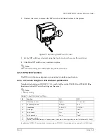
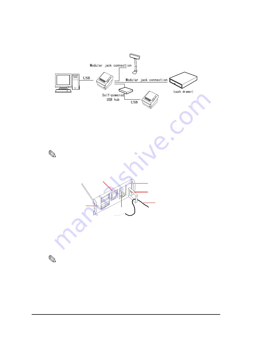
2.4.3.1 USB Interface Connection Diagram
Figure 2-11 USB connection
2.4.3.2 Connecting the USB interface cable
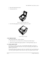
1. Attach the locking wire saddle at the location shown in the figure below.
2. Put the USB cable through the locking wire saddle as shown in the figure below.
Note:
Putting the USB cable through the locking wire saddle, as shown in the figure below, prevents the
cable from coming unplugged.
Figure 2-12 Installing the locking wire saddle
3. Connect the USB cable from the host computer to the USB upstream connector.
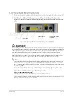
4. Up to 2 USB devices can be connected to a USB model TM-T88III/T88III by using 2 USB
downstream connectors.
Note:
The hub installed in a USB model connector panel is a bus-power-supply hub. It is important to note
that bus-power-supply hubs (including other USB model TM printers) and bus-power-supply
functions with a current consumption of 100 mA or more cannot be connected directly to the printer.
Example:
USB upstream connector
Locking wire saddle
USB cable
DM connector
USB downstream connector
UB-board
Summary of Contents for T88IIIP - TM B/W Thermal Line Printer
Page 1: ...TM T88II T88III Technical reference guide English 405227700 EPSON ...
Page 2: ......
Page 12: ...x Contents Rev A ...
Page 52: ...3 16 Application Development Information Rev A ...
Page 62: ...5 8 Product Specifications Rev A ...
Page 72: ...B 4 Options and Consumables Rev A ...
Page 74: ...C 2 Character Code Tables Rev B C 2 Page 1 Katakana ...
Page 76: ...C 4 Character Code Tables Rev B C 4 Page 3 PC860 Portuguese ...
Page 78: ...C 6 Character Code Tables Rev B C 6 Page 5 PC865 Nordic ...
Page 80: ...C 8 Character Code Tables Rev B C 8 Page 17 PC866 Cyrillic 2 TM T88III only ...
Page 82: ...C 10 Character Code Tables Rev B C 10 Page 19 PC858 Euro ...
Page 86: ...D 2 TM T88II TM 88III Comparison Table Rev A ...
Page 87: ......
Page 88: ...SEIKO EPSON CORPORATION Printed in Japan EPSON ...


