EPSON Stylus Pro 4400/4450/4800/4880/4880C
Revision C
Operating Principles
Printer Mechanism Components
123
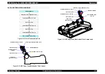
ASF/Pump Motor (Stepping motor)
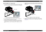
When the transmission path is switched to the Pump Unit side by Carriage
Unit movement and the DE Lock Lever, the ASF/Pump Motor can drive the
ink maintenance system such as pump and wiper, etc.
Movements of the ASF/Pump Motor drive transmission to the Pump Unit side
are shown below.
Note : Rotation of the motor in the clockwise direction as seen from the Motor Pinion
Gear is considered "clockwise".
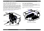
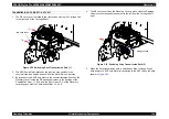
Pump Unit
Ink is sucked from head nozzles by having the pump driven through the
cap (closed). This performs normal ink absorption, initial ink charge,
cleaning, etc. Waste ink from the pump is sent to the Maintenance Tank
through 2 small pipes.
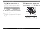
Head Cleaner
A structure of offsetting rubber and felt is used. By wiping/rubbing, ink and
dirt adhering to the head nozzle surface is brushed off.
Cap Assembly
When not printing, the Print Head (should) rest on the Cap Assembly to
ensure that the nozzles don't clog. Also, the Print Head is in the capped
position during ink charging, cleaning, and so on.
Flushing Box
This receives ink ejected during flushing (dummy printing). The flushed ink
flows through the pipe to the Maintenance Tank.
Maintenance Tank (Waste Ink Absorber)
This receives waste ink discharged from the Pump Unit and Flushing Box.
Waste ink is accumulated in a sponge in the Maintenance Tank.
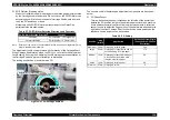
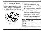
Pump Phase Sensor
A transmissive photosensor is used, which is installed inside the Pump
Unit. This uses the interrupting plate in the Pump Unit to detect the rotation
angle of the pump.
Figure 2-13. Pump Phase Sensor
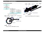
Table 2-5. ASF/Pump Motor Rotation Directions and Functions
ASF/Pump Motor Rotation
Direction
Function
Clockwise
• Pump suction
• Wiper set
Counterclockwise
• Pump release
• Wiper reset
Pump Phase Sensor
Interrupting Plate
Summary of Contents for Stylus Pro 4800 Portrait Edition
Page 9: ...C H A P T E R 1 PRODUCTDESCRIPTION ...
Page 113: ...C H A P T E R 2 OPERATINGPRINCIPLES ...
Page 156: ...C H A P T E R 3 TROUBLESHOOTING ...
Page 200: ...C H A P T E R 4 DISASSEMBLY ASSEMBLY ...
Page 366: ...C H A P T E R 5 ADJUSTMENT ...
Page 448: ...C H A P T E R 6 MAINTENANCE ...
Page 457: ...C H A P T E R 7 APPENDIX ...


