12. External Interface
S5U1C6F632T1/T2 (SVT6F632) Hardware Manual
EPSON
29
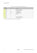
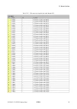
12.2 Expansion connector (CN2)
The CN2 connector specifications and pin layout are as shown below.
Table 12.2 CN2 connector pin layout and connector diagram
CN2 connector
Manufacturer: Hirose Electric
Model: HIF3E-30PA-2.54DSA
(71)
(Upper side)
No.
Name
I/O
Function
1 P00
I/O
General-purpose
port
*1
2 P01
I/O
General-purpose
port
*1
3 P02
I/O
General-purpose
port
*1
4 P03
-
Used
(buzzer)
5
P10
-
Used (push-on switch (SW1))
6
P11
-
Used (push-on switch (SW2))
7
P12
-
Used (push-on switch (SW3))
8
P13
-
Used (push-on switch (SW4))
9
P20
-
Used (pressure sensor interface (SCK))
10
P21
-
Used (pressure sensor interface (MOSI))
11
P22
-
Used (pressure sensor interface (MISO))
12
P23
-
Used (pressure sensor interface (CSB))
13
P30
-
Used (pressure sensor interface (PD))
14
P31
-
Used (pressure sensor interface (DRDY))
15 P32
I/O
General-purpose
port
16
P33
-
Used (illumination sensor power supply control)
17
P40
-
Used (AD converter interface (SCLK))
18
P41
-
Used (AD converter interface (SDAT))
19
P42
-
Used (AD converter interface (XCS))
20 P43
I/O
General-purpose
port
21 P50
I/O
General-purpose
port
22 P51
I/O
General-purpose
port
23 P52
I/O
General-purpose
port
24 P53
I/O
General-purpose
port
25
VDD
-
Power supply pin (positive)
26
VDD
-
Power supply pin (positive)
27
RESET
O
Reset output (positive logic)
28
VSS
-
Power supply pin (negative)
29
VSS
-
Power supply pin (negative)
30
VSS
-
Power supply pin (negative)
*
1
May be used only with the S5U1C6F632T2. (Cannot be used with R/F converter ch0.)
Not connected with S5U1C6F632T1.
C6F632
1
2
29
30
CN2


