4. Usage
10
Seiko Epson Corporation
S5U1C31D50T1 Manual
(Rev.2.0)
4. Usage
4.1 Running Demo Software
The S5U1C31D50T1 board is shipped with the demo software programmed into S1C31D50 mounted on this
board. In the demo software, you can operate the push switches(SW4, SW5, ..., SW10) on the board to run the
sound playback with 2 channel mixing and speed conversion.
The procedure for running the demo software is as follows.
1)
Check that the Jumpers are default setting. (Refer to Section 3.1)
2)
Connect J8 to the speaker via the speaker cable included with the S5U1C31D50T1.
3)
Set the power supply to “VBUS”. (Refer to Section 3.2)
4)
Select the class-AB amplifier with differential input. (Refer to Section 3.3)
5)
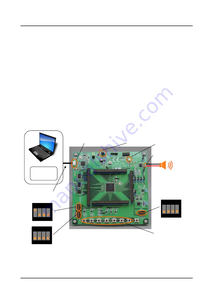
Set the DIP-switches. (Refer to Figure 4.1.1)
6)
Connect CN1(USB) to PC or mobile battery via the micro USB cable to supply the 5V power.
7)
Press SW1(RESET) to reset the S5U1C31D50T1.
8)
Press SW4(PLAY/STOP-CH0) and/or SW5(PLAY/STOP-CH1) to start the sound play.
For details of the demo mode, refer to “4. Demo Software” in “S1C31D50 Peripheral Circuit Sample Software
Manual”
Figure 4.1.1 Layout of Main Parts for Demo Mode
Sound output connector for
class-AB amplifier (J8)
Jumper for power supply
selecting (J12)
Micro USB cable
or
Mobile battery
(5V)
Micro-USB
Connector (CN1)
Push Switches
(SW4/5/6/7/8/9/10)
Reset Switch (SW1)
DIP Switch (SW2)
1
2
3
4
ON
DIP Switch (SW12)
1
2
3
4
ON
DIP Switch (SW3)
1
2
3
4
ON
Summary of Contents for S5U1C31D50T1
Page 1: ...Rev 2 0 CMOS 32 BIT SINGLE CHIP MICROCONTROLLER S5U1C31D50T1 Manual S1C31D50 Evaluation Board ...
Page 17: ...Appendix A Circuit Diagrams 14 Seiko Epson Corporation S5U1C31D50T1 Manual Rev 2 0 ...
Page 18: ...Appendix A Circuit Diagrams S5U1C31D50T1 Manual Seiko Epson Corporation 15 Rev 2 0 ...


