


3. Hardware
Information
S5U1C17564T2 Manual
Seiko Epson Corporation
3
(Rev. 1.0)
3. Hardware
Information
3.1 Layout
information
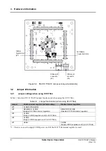
The S5U1C17564T2 component layout is as shown in Figures 3.1 and 3.2.
Figure 3.1 S5U1C17564T2 component layout (upper side)
*1: Connectors J1, J2, J3, and J4 are patterns only, and the actual connectors are provided together with the
product for mounting as necessary.
*2: The through-hole bore diameter is 0.85 mm.
Extension
Connector (J1)
(foot pattern only
*
1
*
2
)
Reset SW
(SW1)
HVDD-IN
(J7)
LVDD-IN
(J8)
AVDD-IN
(J9)
Extension
Connector (J2)
(foot pattern
only
*
1
*
2
)
Extension
Connector (J3)
(foot pattern only
*
1
*
2
)
Extension
Connector (J4)
(foot pattern only
*
1
*
2
)
S1C17564
(U1)
1 Pin
Regulator
Enable/Disable
Select Jumper
(JP2)