4. CPUIF Verification Procedure
10
EPSON
S1R72V17 CPU Connection Guide
(Rev. 1.0)
4. CPUIF Verification Procedure
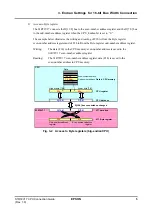
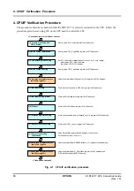
The procedure shown here checks whether the S1R72V17 is correctly connected to the CPU. Follow the
procedure given below, using ICE on the CPU used to control this LSI.
<Connection test start (HW reset cancel)>
Dummy read PM_Control register (0x012 address)
Dummy read CPU_ChgEndian register (0x077h address)
Set CPU_Endian, BusMode, Bus8x16 to the CPU_Config register
Little-endian CPU: 0x74h address
Big-endian CPU: 0x75h address
Dummy read CPU_ChgEndian register (0x077h address)
Read/write test to/from WakeupTim_H,L registers (0x014h address)
Write clock setting value to ClkSelect register (0x73h address)
Write 0x00 to ModeProtect register (0x071 address)
Write 0x00 to ChipReset register (0x011 address)
Write oscillation start time to WakeupTim_H,L registers (0x014 address)
Write 0x40 to PM_Control register (0x012 address)
Read MainIntStat register (0x000 address) to check that
FinishedPM bit (bit 0) is set to “1.”
Read/write test to/from AREA0StartAdrs_L,H registers (0x080 address)
Read/write test to/from D_EPaIntEnb register (0x0C6 address) and
D_EPbIntEnb register (0x0C7 address)
<Connection test end>
1) Recovery processing from
CPU_Cut state
3) CPU operating mode setting
4) Endian setting enabling
5) Asynchronous register access
test (Word register)
6) Clock input setting
7) Clock input setting protect
8) MTM reset
9) Oscillation start time setting
10) Internal clock feed setting
⑦ MTMリセット
11) Internal clock setting
confirmation
12) Synchronous register access
test (Word register)
13) Synchronous register access
test (Byte register)
2) Endian setting initialization
Fig. 4-1 CPU-IF verification procedure


