PhotoPC 2100Z
Revision E
Adjustment
Adjustment
66
4.
Run the LCD adjustment program (CRT21ma.exe) on the PC.
5.
Insert into the camera the CF card in which the LCD adjustment program has been
installed.
6.
Hold down the F Button and Shutter Button together and then press the Playback
Button.
7.
Push the “+” button on the adjustment window of the PC until the adjustment patter
appears on the LCD monitor.(Refer to Figure 5-4.)
8.
While observing the monitor screen of the camera, adjust the brightness, by pressing
the “+” or “-” button on the adjustment window of the PC, so that both the black area
and white area are seen clear at the same time (a maximum contrast is observed).
Figure 5-4. LCD Adjustment Pattern
“+” button
Raise the brightness of LCD.
“-” button
Lower the brightness of the LCD.
9.
Upon completion of brightness adjustment above, press the “Write” button on the
adjustment window of the PC, and the monitor of the camera will display “OK”.
10. Pressing the Shutter Button fully will turn off power to the camera to complete the
adjustment.
11. Remove the CF card from the camera.
12. Disconnect the AC adapter and the communication cable from the camera.
13. Pressing the “e” key will complete the adjustment program.
C A U T I O N
With the PC having two or more serial ports, use COM1 port, if
possible.
When c
onnect
the camera to PC by the RS-232c interface,
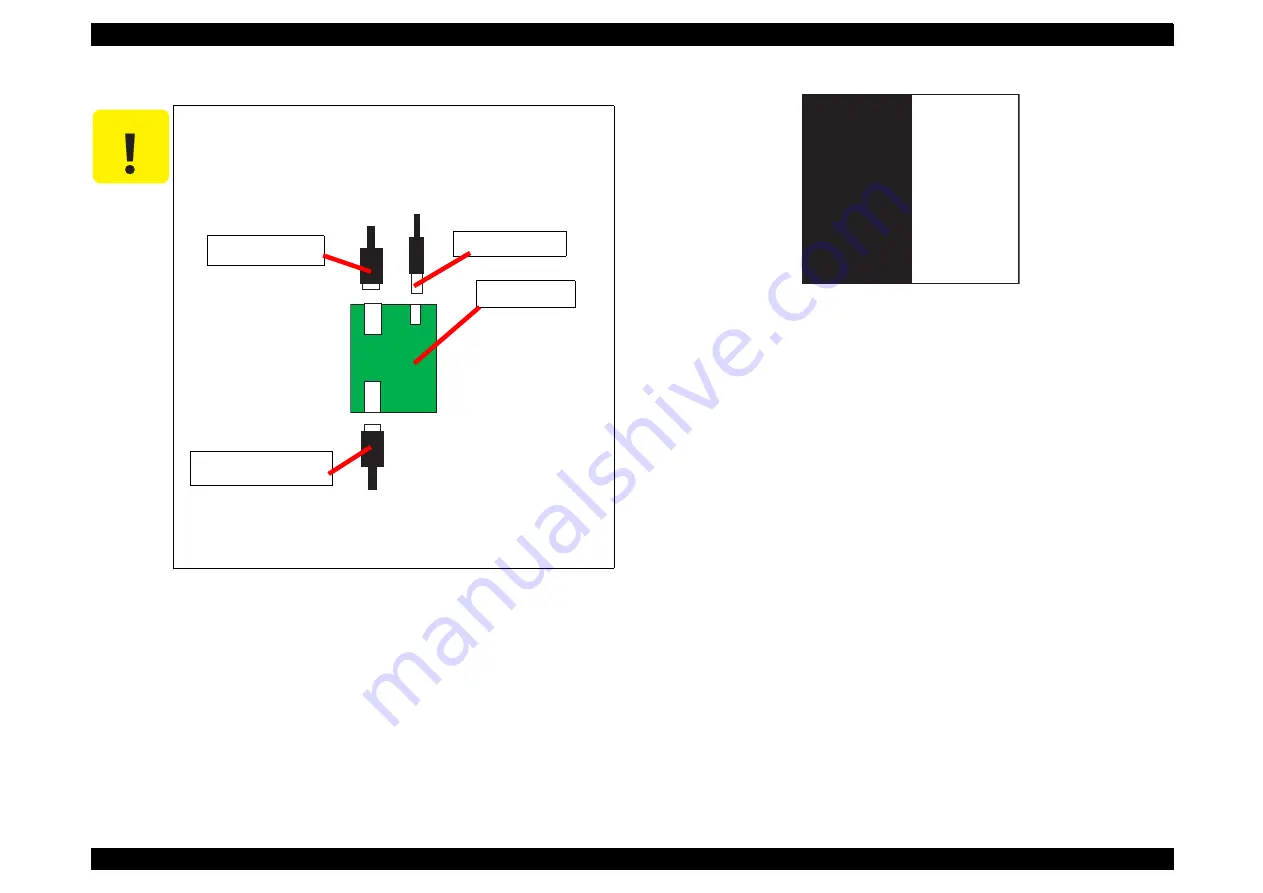
connect the following figure. Do not misconnect the cables,
otherwise the RS-232C interface board may have damage.
Figure 5-3. Cable connection
Connect the AC adopter EU-40
to
the interface as a power
supply.
Serial cable
(For PC)
AC Adopter
RS-232C cable
(For Camera)
RS‑232C
interface
Summary of Contents for PhotoPC 2100Z
Page 1: ...EPSONPhotoPC2100Z Digital Still Camera SERVICE MANUAL SEDC01002 ...
Page 9: ...C H A P T E R 1 PRODUCTDESCRIPTION ...
Page 42: ...C H A P T E R 2 OPERATINGPRINCIPLES ...
Page 44: ...PhotoPC 2100Z Revision A Operating Principles Overview 38 ...
Page 47: ...PhotoPC 2100Z Revision A Operating Principles Overview 41 PS_block7019e pdf ...
Page 49: ...C H A P T E R 3 TROUBLESHOOTING ...
Page 52: ...C H A P T E R 4 DISASSEMBLYANDASSEMBLY ...
Page 65: ...C H A P T E R 5 ADJUSTMENT ...
Page 78: ...C H A P T E R 6 MAINTENANCE ...
Page 80: ...C H A P T E R 7 APPENDIX ...
Page 82: ......
Page 87: ......
Page 88: ......
Page 90: ......
Page 91: ......
Page 92: ......
Page 93: ......
Page 94: ......
Page 95: ......
Page 96: ......
Page 97: ......
Page 98: ......
Page 99: ......
Page 100: ......
Page 108: ......


