


EPSON Perfection V700 Photo
Revision A
6
Contents
Chapter 1 Product Description
1.1 Features.................................................................................................................. 9
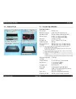
1.2 Scanner Parts ....................................................................................................... 10
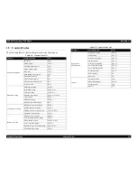
1.3 Scanner Specification .......................................................................................... 10
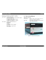
1.4 Exterior Specifications ........................................................................................ 13
1.5 Control Codes...................................................................................................... 15
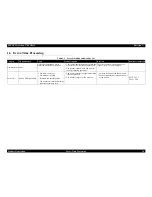
1.6 Error-Time Processing......................................................................................... 16
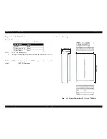
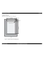
1.7 Maximum Document Size and Placement .......................................................... 17
Chapter 2 Operating Principles
2.1 Engine Operation Outline.................................................................................... 20
2.1.1 Carriage Unit ...............................................................................................20
2.1.2 TPU Carriage Unit Outline..........................................................................21
2.1.3 Drive Mechanism operation ........................................................................22
2.1.4 Dual Lens System ........................................................................................24
2.2 Digital ICE Function Operation .......................................................................... 25
2.2.1 Digital ICE for Photos Overview ................................................................25
2.2.2 Digital ICE for Film Overview....................................................................25
2.3 Circuit Boards...................................................................................................... 27
2.3.1 General View of Circuit Boards ..................................................................27
2.3.2 The Main Board...........................................................................................28
2.3.3 The TPU Main Board ..................................................................................28
2.3.4 Image Processing Operation ........................................................................29
Chapter 3 Troubleshooting
3.1 Overview ............................................................................................................. 31
3.1.1 Self-Diagnosing ...........................................................................................31
3.2 Troubleshooting................................................................................................... 31
Chapter 4 Disassembly / Assembly
4.1 Overview ............................................................................................................. 36
4.1.1 Precautions...................................................................................................36
4.1.2 Recommended Tools ...................................................................................37
4.1.3 Recommended Screws.................................................................................37
4.2 Disassembly Procedure ....................................................................................... 38
4.2.1 Removing the TPU Unit ..............................................................................39
4.2.2 Removing the Upper Housing .....................................................................40
4.2.3 Removing the SUB Board ...........................................................................43
4.2.4 Removing the Panel Board ..........................................................................44
4.2.5 Removing the Main Board ..........................................................................45
4.2.6 Removing the Carriage Unit........................................................................48
4.2.7 Removing the CR Motor .............................................................................50
4.2.8 Removing the Driven Pulley Unit ...............................................................53
4.2.9 Removing TPU Lower Housing ..................................................................54
4.2.10 Removing the TPU Carriage Unit .............................................................55
4.2.11 Removing the TPU Unit Cable..................................................................57
4.2.12 Removing the SUB_B Board and TPU Inverter Board.............................58
4.2.13 Removing the SUB_C Board, SUB_D Board and Lamps ........................59
4.2.14 Removing the DRV Board ........................................................................61
4.2.15 Removing the Hinges ................................................................................62
4.2.16 Removing the TPU CR Motor...................................................................63
4.2.17 Removing Compression Spring 3.15.........................................................65
Chapter 5 Adjustment
5.1 No Special Adjustments ...................................................................................... 67
Chapter 6 Maintenance
6.1 Overview ............................................................................................................. 69
6.1.1 Cleaning.......................................................................................................69
6.1.2 Lubrication...................................................................................................69
Summary of Contents for Perfection V700 Series
Page 1: ...EPSON PerfectionV700Photo Color Image Scanner Service Manual SESC05006 ...
Page 5: ...Revision Status Revision Date of Issue Description A December 20 2005 First release ...
Page 8: ...C H A P T E R 1 PRODUCTDESCRIPTION ...
Page 19: ...C H A P T E R 2 OPERATINGPRINCIPLES ...
Page 30: ...C H A P T E R 3 TROUBLESHOOTING ...
Page 35: ...C H A P T E R 4 DISASSEMBLY ASSEMBLY ...
Page 66: ...C H A P T E R 5 ADJUSTMENT ...
Page 68: ...C H A P T E R 6 MAINTENANCE ...
Page 72: ...C H A P T E R 7 APPENDIX ...
Page 75: ...Model GT X900 Perfection V700 Photo Board B178 MAIN Board Assy MAIN Rev C Sheet 1 1 ...
Page 76: ...Model GT X900 Perfection V700 Photo Board B178 SUB Board Assy SUB Rev A Sheet 1 1 ...
Page 77: ...Model GT X900 Perfection V700 Photo Board B178 PNL Board Assy PNL Rev A Sheet 1 1 ...
Page 78: ...Model GT X900 Perfection V700 Photo Board B178 ISN Board Assy ISN Rev A Sheet 1 1 ...
Page 79: ...Model GT X900 Perfection V700 Photo Board B178 DRV Board Assy DRV Rev A Sheet 1 1 ...
Page 80: ...Model GT X900 Perfection V700 Photo Board B178 SUB B Board Assy SUB B Rev A Sheet 1 1 ...
Page 81: ...Model GT X900 Perfection V700 Photo Board B178 SUB C Board Assy SUB C Rev A Sheet 1 1 ...
Page 82: ...Model GT X900 Perfection V700 Photo Board B178 SUB D Board Assy SUB D Rev A Sheet 1 1 ...
Page 83: ...Model GT X900 Perfection V700 Photo Board B178 SUB E Board Assy SUB E Rev A Sheet 1 1 ...