4-27
EMP-S4
SEIKO EPSON
Revision:B
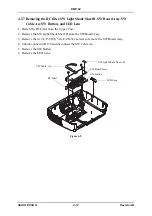
4.2.15 Removing the RC Board Assy, RC Cable B, Safety Switch,
Intake Duct, Intake Fan, and Intake Fan Sheet
1. Remove the RC Board Assy, and disconnect the RC Cable B from the RC Board Assy.
2. Remove the (C.C.P-TITE, 3x8, F/ZN-3C) screw that secures the Safety Switch, and remove
the Safety Switch from the Inner Exhaust Duct.
3. Remove the 5 (C.B.P-TITE, 3x10, F/ZB-3C) screws that secure the Intake Duct to remove
it.
4. Remove the four (C.B.P-TITE SCREW, 3x12, F/ZN-3C) screws that secure the Intake Fan,
and remove the Intake Fan.
5. Remove the Intake Fan Sheet from the Intake Fan.
Figure 4-29.
RC Board Assy.
RC Cable, B
Intake Duct
Intake Fan
Intake Fan
Safety Switch
Intake Fan Sheet
Intake Fan Sheet
Summary of Contents for EMP-S4
Page 1: ...Service Manual Data Projector EMP S4 ...
Page 13: ...Chapter 1 Product Specifications ...
Page 25: ...1 13 EMP S4 SEIKO EPSON Revision B 1 5 External Views Figure 1 8 External Dimensions Unit mm ...
Page 26: ...1 14 EMP S4 SEIKO EPSON Revision B Figure 1 9 External Dimensions Unit Inch ...
Page 27: ...Chapter 2 Theory of Operation ...
Page 49: ...Chapter 3 Troubleshooting ...
Page 63: ...Chapter 4 Disassembly Assembly ...
Page 97: ...Chapter 5 Appendix ...
Page 102: ...5 6 EMP S4 SEIKO EPSON Revision B ...


