background image

SELF TEST

You can run the self test by first turning off the printer
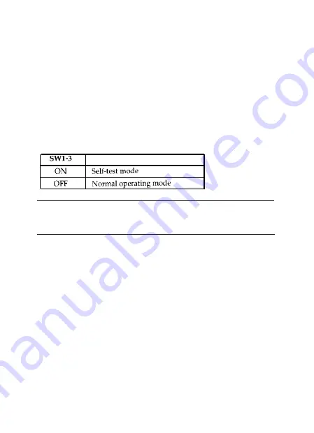
and then turning on DIP switch l-3. When you turn the
power back on, the self test begins. To exit from the self
test, turn off the power and turn DIP switch 1-3 off.

The interface card first checks the RAM condition. After
checking the RAM, data from <30>H to <39>H is sent to

the printer and printed (the printout is only 80 columns
wide).

Table 4. Self-test mode

Note
It takes some time to check the RAM before test printing
beings.

10

Summary of Contents for C82310

Page 1: ...EPSON 32KB Parallel Interface Card C82310 English Deutsch Français Español Italiano 4000402 S01 00 ...

Page 2: ...for radio noise emissions from digital apparatus as set out in the radio interference regulations of the Canadian Depart ment of Communications Le présent appareil numérique n émet pas de bruits radioélectriques dépassant les limites applicables aux appareils numèriques de Class B prescrites dans le réglement sur le brouillage radioélectrique édicté par le Ministère des Communications du Canada WA...

Page 3: ...2KB Parallel Interface Card C82310 32 KB Schnittstellenkarte C82310 Carte d Interface parallèle 32Ko C82310 Módulo de interface en paralelo de 32KB C82310 Scheda dell interfaccia parallela da 32KB C82310 ...

Page 4: ...TION About this guide SETTING THE CONDITIONS Card layout DIP switch and jumper settings DIP switches Jumpers DATA ENTRY About data entry SELF TEST SPECIFICATIONS HARDWARE DESCRIPTION INSTALLATION 2 3 4 4 5 5 7 9 9 10 11 12 15 1 ...

Page 5: ...s parallel data communication between a host computer and an Epson printer This card has the following features Ž A 32 Kbyte buffer that frees up your computer for other uses while your printer continues to print Ž A self test function that can help solve interface problems 2 ...

Page 6: ...ce card in a variety of Epson printers Also included are instructions on how to adjust the settings of the C82310 interface card as well as a general description of parallel data communication The C82310 option package contains the following items C82310 parallel l F Card 3 ...

Page 7: ...o sets of DIP switches and five jumpers These switches and jumpers are used for selecting various interface operations Card layout The figure below shows the layout of the C82310 card and the locations of the DIP switches and jumpers Figure 2 Card layout 4 ...

Page 8: ...aution Always turn the power off before changing DIP switch and jumper settings New settings take effect when the printer is turned back on DIP switches Setting DIP switches allows you to change interface functions The two sets of switches are labeled SW1 and SW2 SW1 contains several individual toggle type switches that can be set either on or off The individual switches are referred to by set SW1...

Page 9: ...able 1 DIP switch 1 Note When DIP switch l l is set to ON the interface card can continue store data in the buffer memory even though the printer is in an OFF LINE or PAUSE state Switch 2 The table below contains information on switch 2 Table 2 Switch 2 Function O N OFF Factory setting The I F card enable disable Enable Disable ON 6 ...

Page 10: ...ter to select the optional interface Jumpers A jumper is a small plug used for connecting or discon necting a circuit The jumper is on when the jumper plug covers both wires of the terminal Jumper settings can be changed by either attaching or removing the rectangular jumper plug If the jumper is to be turned off connect it to only one of the two terminal pins as shown in the figure below This pre...

Page 11: ...over both terminals while OFF means you disconnection of the jumper Table 3 Jumper settings Jumper Function Factory setting J1 Fixed See Note J2 Fixed See Note J3 Fixed See Note J4 Fixed See Note JG ON Connect chassis ground to signal OFF ground Note Jl J2 J3 and J4 jumpers are connected at the factory do not change these setting 8 ...

Page 12: ...fer that temporarily stores data before it is printed When this buffer becomes full the interface card send a BUSY signal Reception of data during this state cannot be guaranteed The data in the buffer is automatically sent to the printer when the printer indicates it is ready to accept more data 9 ...

Page 13: ...est begins To exit from the self test turn off the power and turn DIP switch 1 3 off The interface card first checks the RAM condition After checking the RAM data from 30 H to 39 H is sent to the printer and printed the printout is only 80 columns wide Table 4 Self test mode Note It takes some time to check the RAM before test printing beings 10 ...

Page 14: ...al supplied STROBE pulse 3 Handshaking Via ACKNLG or BUSY signals 4 Logic level TTL level 5 RAM capacity 32 Kbytes 6 Connector 57 30360 Amphenol 36 pin or its equivalent Interface timing The figure below shows the timing for the parallel interface Figure 3 Interface timing 11 ...

Page 15: ...onds at the receiving terminal These signals represent data in bits 1 to 8 of parallel data respectively Each signal is high when data is logical 1 and low when it is logical 0 About a 12 µseconds pulse Low indicates that data has been received and that the interface card is ready to accept more data This signal is output paired together with a BUSY signal A high signal indicates that the interfac...

Page 16: ... 5 This function depends on printer specifications Not used Twisted pair return signal g r o u n d Printer s chassis ground which is isolated from the logical ground Not used Twisted pair return signal ground When the signal level goes low the printer controller and the interface card are reset This signal level is usually high its pulse width must be more than 50 µseconds at the receiving termina...

Page 17: ...ixed low by changing a DIP switch jumper or SelecType setting on the printer The printer monitors this signal so this signal s function depends on the printer s specifications Note The column heading Direction refers to the direction of signal flow as viewed from the printer All interface conditions are based on TTL level Both the rise and fall of each signal must be less than 0 2 µseconds 14 ...

Page 18: ... Turn off the power to the printer and the computer before installing Make sure that all power and interface cables are removed Avoid touching the printer s circuit board contacts many components are sensitive to static electric charges that may build up on your body 1 Adjust DIP switch and jumper settings as necessary 2 Align both sides of this card with the guides on the sides of the interface c...

Page 19: ...3 Insert firmly until the interface pins mate with connector inside your printer 4 Attach the two screws to secure the interface 16 ...

Page 20: ...099 SESTO S GlOVANNl MI Italy Phone 2 262331 Fax 2 2440750 SEIKO EPSON CORPORATION Hirooka Office 80 Harashinden Hirooka Shiojiri Shi Nagano ken 399 07 Japan Phone 0263 52 2552 EPSON DEUTSCHLAND GmbH Zülpicher Straße 6 4000 Düsseldorf 11 F R Germany Phone 0211 56030 Telex 8584786 EPSON FRANCE S A 68 bis rue Marjolin 92300 Levallols Perret France Phone 1 4087 3737 Telex 610657 EPSON SINGAPORE PTE L...

Page 21: ...EPSON Printed in Japan 91 03 2 ...

Reviews: