EPSON AcuLaser C4000/C4100/C3000
Revision F
Disassembly and Assembly
Disassembly Assembly Procedures
4-436
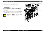
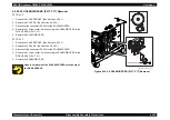
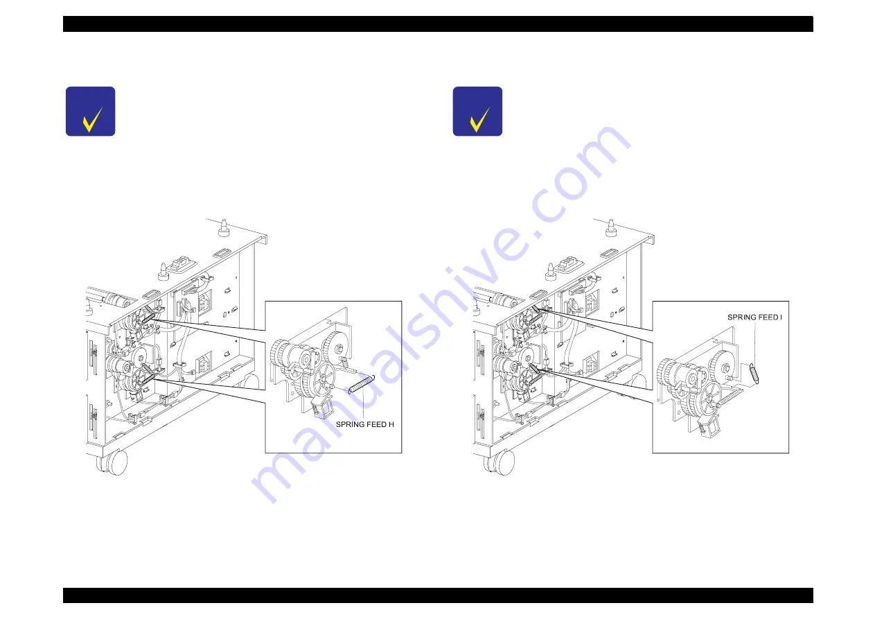
4.2.20.23 SPRING FEED H (PL17.3.10) Removal
1. Remove the COVER FRONT. (See Section 4.2.20.1.)
2. Remove the COVER R. (See Section 4.2.20.2.)
3. Remove the SPRING FEED H.
Figure 4-141. SPRING FEED H (PL17.3.10) Removal
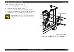
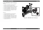
4.2.20.24 SPRING FEED 1 (PL17.3.9) Removal
1. Remove the COVER FRONT. (See Section 4.2.20.1.)
2. Remove the COVER R. (See Section 4.2.20.2.)
3. Remove the SPRING FEED 1.
Figure 4-142. SPRING FEED 1 (PL17.3.9) Removal
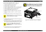
C H E C K
P O I N T
The following steps is a common to the TRAY 2 and the
TRAY 3.
HANABI_FDR_CHAP03_024FD
C H E C K
P O I N T
The following steps is a common to the TRAY 2 and the
TRAY 3.
HANABI_FDR_CHAP03_025FD
Summary of Contents for AcuLaser C3000 Series
Page 20: ...C H A P T E R 1 PRODUCTDESCRIPTIONS ...
Page 71: ...C H A P T E R 2 OPERATINGPRINCIPLES ...
Page 118: ...C H A P T E R 3 TROUBLESHOOTING ...
Page 318: ...C H A P T E R 4 DISASSEMBLYANDASSEMBLY ...
Page 472: ...C H A P T E R 5 ADJUSTMENT ...
Page 477: ...C H A P T E R 6 MAINTENANCE ...
Page 491: ...C H A P T E R 7 AcuLaserC4100 ...
Page 548: ......
Page 549: ......
Page 550: ......
Page 551: ......
Page 552: ......
Page 553: ......
Page 554: ......
Page 555: ...C H A P T E R 8 AcuLaserC3000 ...
Page 579: ...Model AcuLaser C3000 Board C569MAIN BOARD Sheet 1 of 5 Rev B ...
Page 580: ...Model AcuLaser C3000 Board C569MAIN BOARD Sheet 2 of 5 Rev B ...
Page 581: ...Model AcuLaser C3000 Board C569MAIN BOARD Sheet 3 of 5 Rev B ...
Page 582: ...Model AcuLaser C3000 Board C569MAIN BOARD Sheet 4 of 5 Rev B ...
Page 583: ...Model AcuLaser C3000 Board C569MAIN BOARD Sheet 5 of 5 Rev B ...
Page 584: ...C H A P T E R 9 APPENDIX ...
Page 674: ......
Page 675: ......
Page 676: ......
Page 677: ......
Page 678: ......
Page 679: ......
Page 680: ......

