EPSON AcuLaser C4000/C4100/C3000
Revision F
Disassembly and Assembly
Disassembly Assembly Procedures
4-393
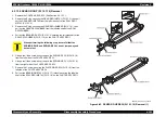
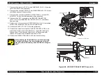
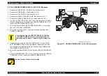
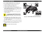
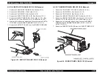
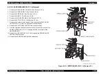
4.2.15.4 HOLDER TONER ASSY (C) (PL12.2.3) Removal
1. Remove the COVER ASSY TOP MAIN. (See Section 4.2.4.4.)
2. Remove the COVER SIDE L. (See Section 4.2.4.14.)
3. Remove the COVER SIDE R. (See Section 4.2.4.9.)
4. Remove the HOLDER TCRU ASSY UNIT. (See Section 4.2.15.1.)
5. Remove the HOLDER TONER ASSY (K). (See Section 4.2.15.5.)
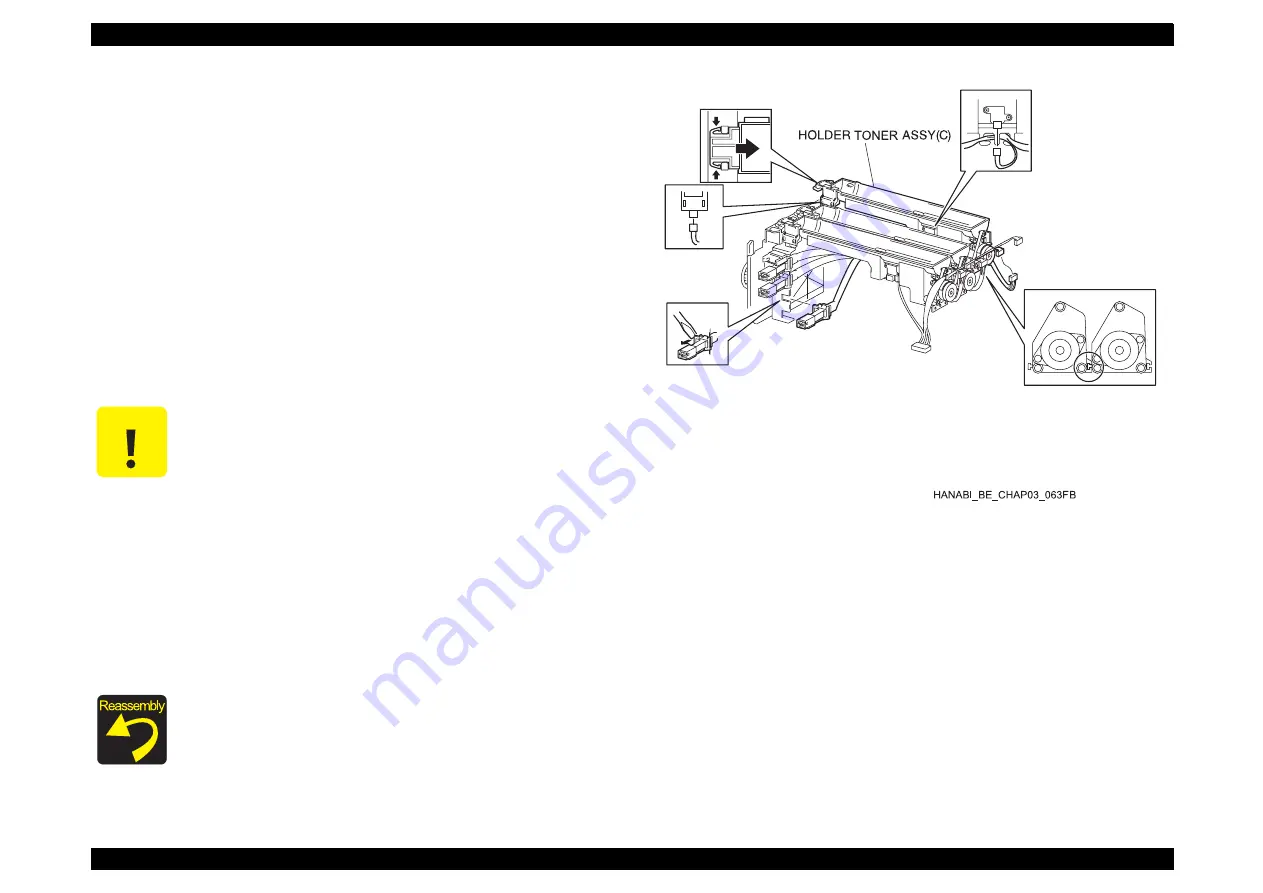
6. From the HOLDER TCRU ASSY UNIT, use a small screwdriver to release
the hook securing the toner emitter of the HOLDER TONER ASSY (C) to
the PLATE ASSY DISPENSER (PL12.3.1).
7. Pull out the toner emitter on the HOLDER TONER ASSY (C) to the right
from the PLATE ASSY DISPENSER.
8. Pull out the connector (P/J513) of the motor from the right side of the
HOLDER TONER ASSY.
9. Release the hook fixing the HOLDER TONER ASSY (C) to the PLATE
ASSY DISPENSER, slide it to the right side and release the motor side
hook, shift the motor side toward the rear and open a gap between it and
the HOLDER TONER ASSY (M).
10. Pull out the connectors (P/J443, P/J433) from the HOLDER TONER ASSY
(C).
11. Free the HARNESS ASSY TNR (PL12.1.6) from the hook on the HOLDER
TONER ASSY (C) and remove the HOLDER TONER ASSY (C).
Figure 4-91. HOLDER TONER ASSY (C) (PL12.2.3) Removal
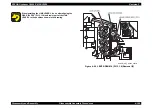
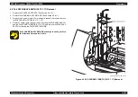
C A U T I O N
In the following step, the HOLDER TCRU ASSY UNIT and
the HOLDER TONER ASSY (C) are kept connected to the
printer body with a harness. Therefore, does not move too
far.
Be sure to attach the hook of motor side.
Summary of Contents for AcuLaser C3000 Series
Page 20: ...C H A P T E R 1 PRODUCTDESCRIPTIONS ...
Page 71: ...C H A P T E R 2 OPERATINGPRINCIPLES ...
Page 118: ...C H A P T E R 3 TROUBLESHOOTING ...
Page 318: ...C H A P T E R 4 DISASSEMBLYANDASSEMBLY ...
Page 472: ...C H A P T E R 5 ADJUSTMENT ...
Page 477: ...C H A P T E R 6 MAINTENANCE ...
Page 491: ...C H A P T E R 7 AcuLaserC4100 ...
Page 548: ......
Page 549: ......
Page 550: ......
Page 551: ......
Page 552: ......
Page 553: ......
Page 554: ......
Page 555: ...C H A P T E R 8 AcuLaserC3000 ...
Page 579: ...Model AcuLaser C3000 Board C569MAIN BOARD Sheet 1 of 5 Rev B ...
Page 580: ...Model AcuLaser C3000 Board C569MAIN BOARD Sheet 2 of 5 Rev B ...
Page 581: ...Model AcuLaser C3000 Board C569MAIN BOARD Sheet 3 of 5 Rev B ...
Page 582: ...Model AcuLaser C3000 Board C569MAIN BOARD Sheet 4 of 5 Rev B ...
Page 583: ...Model AcuLaser C3000 Board C569MAIN BOARD Sheet 5 of 5 Rev B ...
Page 584: ...C H A P T E R 9 APPENDIX ...
Page 674: ......
Page 675: ......
Page 676: ......
Page 677: ......
Page 678: ......
Page 679: ......
Page 680: ......


