EPSON AcuLaser C4000/C4100/C3000
Revision F
Disassembly and Assembly
Disassembly Assembly Procedures
4-346
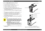
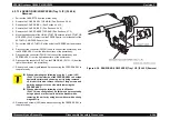
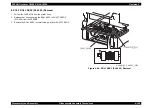
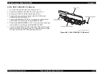
4.2.7.15 ACTUATOR NO PAPER (PL4.3.5) Removal
1. Pull out the CASSETTE from the printer body.
2. Remove the COVER ASSY TOP MAIN. (See Section 4.2.4.4.)
3. Remove the COVER SIDE L. (See Section 4.2.4.14.)
4. Remove the COVER SIDE R. (See Section 4.2.4.9.)
5. Remove the COVER CASSETTE REAR. (See Section 4.2.7.2.)
6. Move the shaft socket of the LINK ACTUATOR secured to the ACTUATOR
NO PAPER (PL4.3.6) away from the FEEDER parts, the let the shaft of the
ACTUATOR NO PAPER come free.
7. Pull out the LINK ACTUATOR of the hole of the FEEDER part and remove
it.
8. Disconnect the connector (P/J2361) used to connect the printer body and
the FEEDER ASSY from the left side surface of the printer body.
9. Disconnect the connector (P/J210) that connect the printer body and
FEEDER ASSY from the right side surface of the printer body.
10. Disconnect the connector (P/J47) on the PWB DRIVE (PL15.1.15) from the
right side surface of the printer body.
11. Remove the 8 screws (gold, tapped, 8mm) securing the FEEDER ASSY to
the printer body.
12. Remove the 4 screws (L85) with a washer securing the FEEDER ASSY to
the printer body.
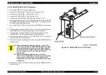
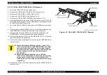
Figure 4-39. ACTUATOR NO PAPER (PL4.3.5) Removal
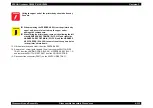
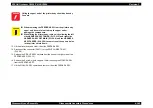
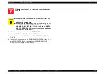
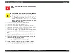
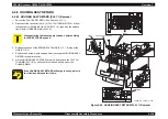
C A U T I O N
When performing the following step, the 1 screw (L85)
(PL4.1.13) at the left side of the FEEDER ASSY can scrape
against the printer body housing as it is being removed,
so it is better to also remove the other 3 long screws and
hold the body parts to the side while removing the
FEEDER ASSY.
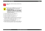
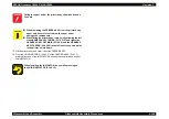
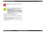
When performing the following step, the Washer
(PL4.1.14) can easily fall out, so this may be prevented by
using a punch or other tool to hold the washer while
removing the part or by using a screwdriver with a strong
magnetic tip.
LEFT
TOP
RIGHT
HANABI_BE_CHAP03_139FA
Summary of Contents for AcuLaser C3000 Series
Page 20: ...C H A P T E R 1 PRODUCTDESCRIPTIONS ...
Page 71: ...C H A P T E R 2 OPERATINGPRINCIPLES ...
Page 118: ...C H A P T E R 3 TROUBLESHOOTING ...
Page 318: ...C H A P T E R 4 DISASSEMBLYANDASSEMBLY ...
Page 472: ...C H A P T E R 5 ADJUSTMENT ...
Page 477: ...C H A P T E R 6 MAINTENANCE ...
Page 491: ...C H A P T E R 7 AcuLaserC4100 ...
Page 548: ......
Page 549: ......
Page 550: ......
Page 551: ......
Page 552: ......
Page 553: ......
Page 554: ......
Page 555: ...C H A P T E R 8 AcuLaserC3000 ...
Page 579: ...Model AcuLaser C3000 Board C569MAIN BOARD Sheet 1 of 5 Rev B ...
Page 580: ...Model AcuLaser C3000 Board C569MAIN BOARD Sheet 2 of 5 Rev B ...
Page 581: ...Model AcuLaser C3000 Board C569MAIN BOARD Sheet 3 of 5 Rev B ...
Page 582: ...Model AcuLaser C3000 Board C569MAIN BOARD Sheet 4 of 5 Rev B ...
Page 583: ...Model AcuLaser C3000 Board C569MAIN BOARD Sheet 5 of 5 Rev B ...
Page 584: ...C H A P T E R 9 APPENDIX ...
Page 674: ......
Page 675: ......
Page 676: ......
Page 677: ......
Page 678: ......
Page 679: ......
Page 680: ......

