EPSON AcuLaser C4000/C4100/C3000
Revision F
Disassembly and Assembly
Disassembly Assembly Procedures
4-304
4.2 Disassembly Assembly Procedures
This section describes procedures for disassembling/assembling the printer.
Unless otherwise specified, assembly can be performed by reversing the
disassembly procedure. In principle, you are to remove all options before
servicing. However, you can leave them if possible.
NOTE:
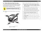
Directions used in this section are defined as shown in the figure
below:
Figure 4-1. Directions
Refer to the followings which explain descriptions used in this chapter.
C A U T I O N
Some parts are listed as spare parts but not mentioned in
disassembly/assembly procedure. Therefore, look
carefully how they are installed before you removing them.
Rear
Left
Front
Right
Regarding “(PL X, Y, Z)” at the end of each heading of removal
sections, it corresponds to the numbers in the part list in Appendix.
Referring to the numbers, you can find the appearance and location
of the parts efficiently.
Directions are described as mentioned below. (See Figure 4-1.)
Front: Front side viewing the printer toward its front side
Back: Rear side viewing the printer toward its front side
Left: Left hand side viewing the printer toward its front side
Right: Right hand side viewing the printer toward its front side
Screws are mentioned with descriptions including “(mounting
location, color, feature, thread part length, and so on)”.
The number in drawing corresponds to the step number in the
section.
Secre the screws in the drawings using a Philips screw driver if no
instruction is given.
If black arrows are shown with numbers, they show the order to act
for the step.
Refer to Appendix for the connector (P/J) locations and harness
routings.
Summary of Contents for AcuLaser C3000 Series
Page 20: ...C H A P T E R 1 PRODUCTDESCRIPTIONS ...
Page 71: ...C H A P T E R 2 OPERATINGPRINCIPLES ...
Page 118: ...C H A P T E R 3 TROUBLESHOOTING ...
Page 318: ...C H A P T E R 4 DISASSEMBLYANDASSEMBLY ...
Page 472: ...C H A P T E R 5 ADJUSTMENT ...
Page 477: ...C H A P T E R 6 MAINTENANCE ...
Page 491: ...C H A P T E R 7 AcuLaserC4100 ...
Page 548: ......
Page 549: ......
Page 550: ......
Page 551: ......
Page 552: ......
Page 553: ......
Page 554: ......
Page 555: ...C H A P T E R 8 AcuLaserC3000 ...
Page 579: ...Model AcuLaser C3000 Board C569MAIN BOARD Sheet 1 of 5 Rev B ...
Page 580: ...Model AcuLaser C3000 Board C569MAIN BOARD Sheet 2 of 5 Rev B ...
Page 581: ...Model AcuLaser C3000 Board C569MAIN BOARD Sheet 3 of 5 Rev B ...
Page 582: ...Model AcuLaser C3000 Board C569MAIN BOARD Sheet 4 of 5 Rev B ...
Page 583: ...Model AcuLaser C3000 Board C569MAIN BOARD Sheet 5 of 5 Rev B ...
Page 584: ...C H A P T E R 9 APPENDIX ...
Page 674: ......
Page 675: ......
Page 676: ......
Page 677: ......
Page 678: ......
Page 679: ......
Page 680: ......


