EPSON Stylus COLOR 900/900N
Chapter 2 Operating Principles
41
2.3 Electrical Circuit Operation Principles
The EPSON Stylus Color 900/900N contains the following circuit
boards:
C265 main board
C265 PSB/PSE board
C265 Panel Board
2.3.1 C265 PSB/PSE Power Supply Board
The C265 PSB/PSE power supply board uses a switching regulator
system. It coverts AC line voltage into smooth, filtered DC current at two
voltage levels:
5 VDC for powering the sensors and main logic board
42 VDC for powering the printhead, carriage motor, paper feed
motor, and pump/ASF motor
There are two versions of the power supply board:
the PSB or 120 VAC version (for use in the United States)
the PSE or 220-240 VAC verion (for use abroad)
The power supply board incorporates overvoltage protection to detect
any abnormal rise in output voltage caused by a defect in the circuit. If
the 42 volt output rises to 48 volts, or the 5 volt output rises to 7 volts,
the power supply board shuts itself off. Once it’s deactivated, it cannot
recover until you turn the printer off and then back on.
The power supply circuit also includes a voltage drop delay circuit.
When you turn off the printer by pressing the external power button, the
delay circuit keeps the power supply on long enough for the printer to
complete its power-off operations (paper ejection and printhead
capping). After a pre-determined length of time, the power supply shuts
itself off.
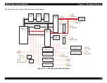
See
, which provides a block-diagram schematic of the
power supply.
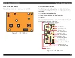
Figure 2-8. Component Layout of C265 PSB/PSE Board
W A R N I N G
The external power switch is only a secondary switch
in the power supply circuit. The primary side of the
power supply is always “hot,” even when the printer
appears to be off. Always unplug the printer before
servicing.
Never touch the heat sink on the Q1 FET with your
bare hands. It is not electrically insulated.
T 1
( t r a n s f o r m e r )
Q 1 ( F E T )
I C 5 1
( + 5 V r e g u l a t o r )
D 5 1
( d i o d e )
L 1 ( n o i s e r e d u c i n g
r e a c t a n c e )
D 5 5
( d i o d e )
C 1 1 ( f o r s m o o t h i n g )
F 1 ( F u s e )
C 1 ( N o i s e
r e d u c i n g c a p a c i t o r )
C N 3
C N 2
C N 1
D a n g e r !
Summary of Contents for 900N
Page 1: ...EPSONStylusCOLOR900 900N Color ink jet printer TM SC900 N 6 59 0 18 ...
Page 8: ... 37 5 PRODUCTDESCRIPTION ...
Page 37: ... 37 5 OPERATINGPRINCIPLES ...
Page 67: ... 37 5 TROUBLESHOOTING ...
Page 89: ... 37 5 DISASSEMBLYANDASSEMBLY ...
Page 121: ... 37 5 ADJUSTMENTS ...
Page 156: ... 37 5 MAINTENANCE ...
Page 169: ... 37 5 APPENDIX ...
Page 179: ...EPSON Stylus COLOR 900 900N Chapter 7 Appendix 176 Figure 7 3 C265 Main Board Soldering side ...
Page 181: ...EPSON Stylus COLOR 900 900N Chapter 7 Appendix 178 Figure 7 6 C265 PNL Board ...
Page 195: ...06 03 01 02 for S E ASIA 03 03 05 03 04 EPSON STYLUS COLOR 900 No 7 10056 Rev 01 ...
Page 197: ......
Page 198: ......
Page 199: ......
Page 200: ......
Page 201: ......


