EPSON Stylus PHOTO 875DC
Revision A
ADJUSTMENT
Adjustment
42
4.
According to the board(s) you replaced, select the item from the list
and click
OK
!
If you have replaced control board for the printer part, select the
top item. The service program refers to the USB ID of the control
board in the card reader part and inputs the corresponding USB ID
for the new board.
!
If you have replaced control board for the card reader part, select
the middle item. The service program refers to the USB ID of the
control board in the printer part and inputs the corresponding
USB ID for the new board.
!
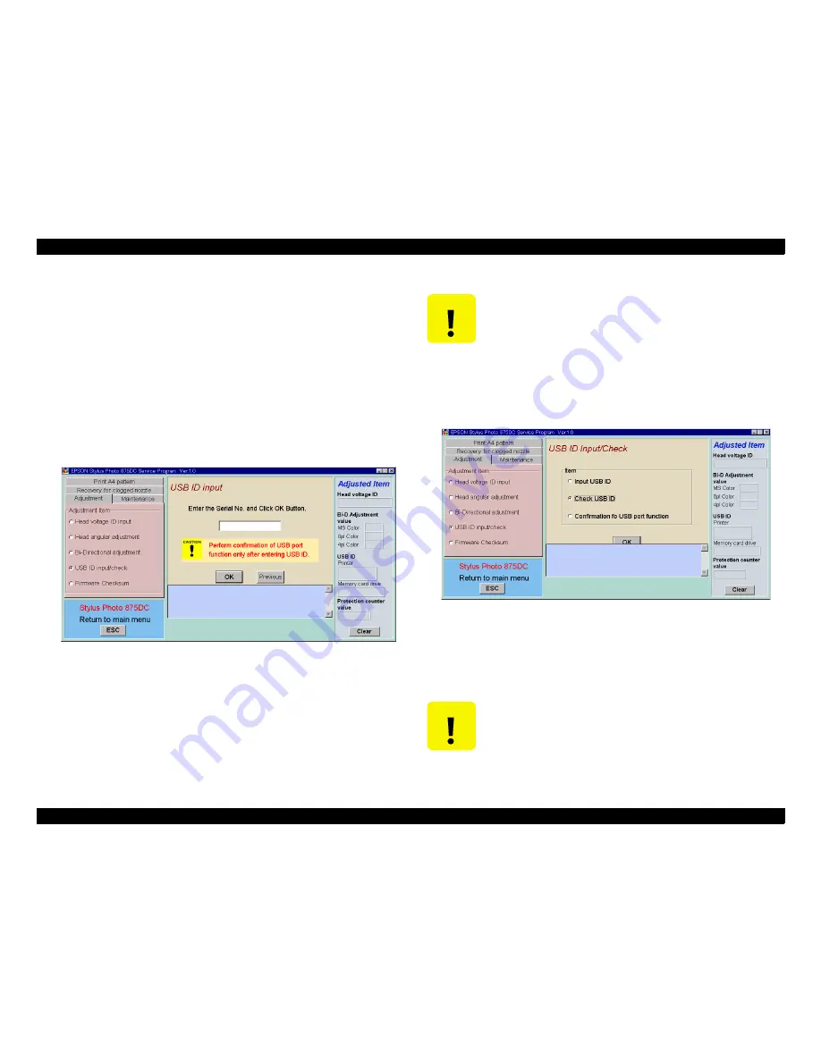
If you have replaced the both boards, the following screen
appears.
Figure 5-5. USB ID Input Window (2)
5.
Get the 10-digit serial number at the back of the printer.
6.
Type the serial number in the window and click
OK
. The new USB ID
is indicated in the bottom window.
7.
Quit the service program.
8.
Turn the printer power off.
9.
Turn the printer power back on.
10. Start the service program again.
11. Select
Check USB ID
in the USB ID Input/Check window and click
OK
.
Both USB IDs are displayed in the bottom window.
Figure 5-6. USB ID Input Window (3)
12. Select
Confirmation of USB port function
and click OK, and the
confirmation of the USB port function window appears. In the
window, click OK. If the USB port connection is established properly,
A4 pattern will print.
C A U T I O N
If you input USB ID, be sure to quit the service program and
turn the printer power off. Otherwise, the new USB ID is
not stored in the control board.
C A U T I O N
!
Even though you type a wrong serial number, the service
program accepts it. Therefore, be sure to type the serial
number exactly.
!
Setting values are not effective until the printer power is
next turned on since they are stored in EEPROM when the
printer is turned off.
Summary of Contents for 875DC - Stylus Photo Color Inkjet Printer
Page 8: ...C H A P T E R 1 PRODUCTDESCRIPTIONS ...
Page 20: ...C H A P T E R 2 OPERATINGPRINCIPLES ...
Page 25: ...C H A P T E R 3 TROUBLESHOOTING ...
Page 27: ...C H A P T E R 4 DISASSEMBLYANDASSEMBLY ...
Page 37: ...C H A P T E R 5 ADJUSTMENT ...
Page 45: ...C H A P T E R 6 MAINTENANCE ...
Page 47: ...C H A P T E R 7 APPENDIX ...
Page 62: ......
Page 63: ......
Page 64: ......
Page 65: ......
Page 66: ......


