
BEIJING EPSOLAR TECHNOLOGY CO., LTD. Tel
:
+86-10-82894112 / 82894962 Website
:
www.epsolarpv.com/www.epever.com
3 4
The surface of the inverter produce high temperature when it is working
,
please stay away from materials or equipment which affected by high
temperature
This inverter can only be used singly, parallel connection or in series will
damage the inverters.
It’s an off-grid inverter, if connect to the grid, the inverter may be
damaged.
2)
Wiring
NOTE:
If the output is connect the different load, it is suggested
that the large shock current load is turn on firstly, then the small
shock current is turn off.
NOTE
:
Turn off the inverter, and then cut off the DC input power
supply when the load stops working.
WARNING
:
When the inverter polarity reversed, the fuse or
inverter will be damaged.
WARNING
:
Be careful the electric shock risk, the AC port will
output the high voltage.
WARNING
:
DO NOT open the product cover or where the
children can't reach to prevent electric shock.
WARNING
:
Please contact the professional, when the inverter
occur the faults
4.Protection
Protection
and recover
Condition
Phenomenon
Parameter
IP350-12
IP350-22
Over voltage
protection
and recover
Input
Voltage
Ui(±2%)
Ui>16V
Ui>32V
Output is OFF
Green indicator fast flashing
Buzzer sounds
Ui≤14.5V
Ui≤29V
Green indicator on solid
The output is on
Low voltage
protection
and recover
Input
Voltage
Ui(±2%)
Ui<10.5V
Ui<21V
Output is OFF
Green indicator slowly flashing
Buzzer sounds
Ui≥12.5V
Ui≥25V
Green indicator on solid
The output is on
Over tem.
protection
and recover
Tem.(T)
IP350-12:
Heat sink T
≥75
℃
IP350-22:
Heat sink T
≥70
℃
Internal T
≥65
℃
Inverter turn OFF
Heat sink T
≤65
℃
Internal T
≤55
℃
Inverter turn ON
Limit power
protection
①
and recover
Output
power (S)
S
0
=280W
320W≤S<360W
Output is OFF after 15min
Red indicator slowly flashing
Buzzer sounds
360W≤S<380W
Output is OFF after 1min
Red indicator slowly flashing
Buzzer sounds
S≥380W
Output is OFF after 10s
Red indicator slowly flashing
Buzzer sounds
S>Rated input power
Output is OFF after 5s
Red indicator slowly flashing
Buzzer sounds
Load short circuit
①
Output is OFF immediately
Red indicator fast flashing
Buzzer sounds
①
When the load occur limit power protection and short circuit protection, it has
three times recover output function (once delay 5s, twice delay 10s and three times
delay 15s).
5. Troubleshooting
Faults
Possible reasons
Troubleshooting
Green indicator
slowly flashing
Buzzer sounds
Low DC input
voltage
Measure the DC input voltage with
multimeter, if the voltage is lower than
10.8V/21.6V. Adjust the input voltage to
restore normally.
Green indicator
fast flashing
Buzzer sounds
High DC input
voltage
Measure the DC input voltage with
multimeter, if the voltage is lower than
16V/32V. Adjust the input voltage to
restore normally.
Red indicator
slowly flashing
Buzzer sounds
Overload
①
Reduce the number of the AC load.
②
Restart the inverter.
Red indicator
fast flashing
Buzzer sounds
Short circuit
①
Check carefully loads connection,
clear the fault.
②
Restart the inverter.
Green and red
indicator on solid
Buzzer sounds
Over temperature
When the heat sink temperature exceeds
75
℃
or the internal temperature exceeds
65
℃
, the inverter will automatically cut
output circuit; When the heat sink
temperature below 65
℃
or the internal
temperature below 55
℃
, the inverter will
resume to work.
6.Technical Specifications
Technical Parameters
Model
Item
IP350-12
IP350-22
Input Rated Voltage
12VDC
24VDC
Input Voltage Range
10.8
~
16VDC
21.6
~
32VDC
Input surge voltage
<
32V
<
44V
Fuse
32VDC/50A
32VDC/30A
No-load current
<
0.7A
<
0.5A
Output Voltage
220VAC(±5%)
230VAC(-10%
~
+5%)
Output Continuous
Power
350VA(-20
℃~
+45
℃
)
Power factor
0.8
Instantaneous impact
power
≥750VA
Output way
Single phase
Output Wave
Pure sine wave
Output Frequency
50/60Hz
(
±0.2%
)
Distortion THD
THD
≤5%(Resistive load)
Max. Efficiency
91%
USB Output
5VDC/1A
Environmental Parameters
Working environment
temperature
-20
℃~
+45
℃
Storage temperature
range
-35
℃~
+70
℃
Humidity range
≤93%
(
N.C.
)
Enclosure
IP20
Altitude
<2000m
(Derating to operate according to IEC62040 at a
height exceeding 1000 m)
Mechanical Parameters
DC input terminal
6mm
2
Overall dimension
221×106.5×67.5mm
Mounting dimension
193mm
Mounting hole size
Φ4.2mm
Net weight
0.9kg
7. Disclaimer
This warranty does not apply under the following conditions:
Damage from improper use or use in an unsuitable environment.
Battery voltage exceeding the rated value of inverter.
User disassembly or attempted repair the inverter without permission.
The inverter is damaged due to natural elements such as lighting.
The inverter is damaged during transportation and shipment.
Any changes without prior notice! Version number
:
V1.0
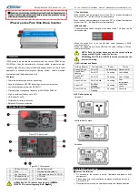
Figure 1 DC Input
Figure 2 DC Output
Operation Steps
:
Step1:
Turn off the inverter.
Step2:
Connect the AC load to the AC outlet.
Step3:
Connect the battery.
Step4:
Turn on the inverter.
Step5:
Turn on the AC load.


