© EPS Stromversorgung in 2022, this information is subject to change without notice
38
30000800_manual_psb_10000_4u_30kw_en_04
2.3.6.2
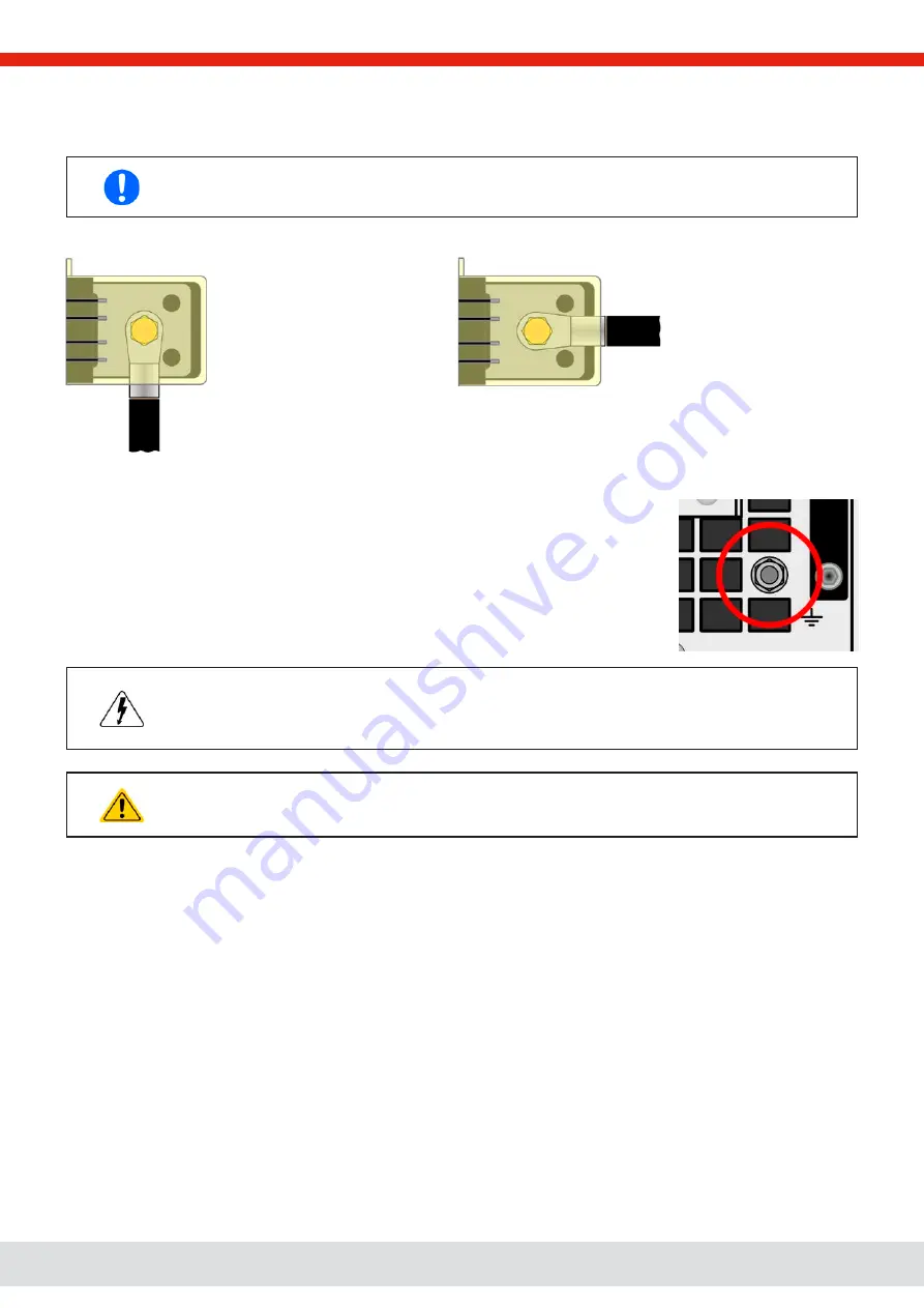
Cable lead and plastic cover
The scope of delivery included a plastic cover for the DC terminal which serve as contact protection. It must always be in-
stalled when operating the device. There are breakouts so that the DC cables can be laid in various directions.
The connection angle and the required bending radius for the DC cable must be taken into account when
planning the depth of the complete device, especially when installing in a 19” cabinet or similar installa-
tions.
Examples for the type 1 terminal:
•
90° up or down
•
space saving in depth
•
no bending radius
•
horizontal lead
•
space saving in height
•
large bending radius
2.3.7
Grounding of the DC terminal
Besides the main purpose of grounding the enclosure, the extra grounding point (item “7” in
1.8.4.3 or “8” in 1.8.4.8) can be used to ground any the DC terminal poles. Doing so causes
a potential shift on the opposite pole against PE. Because of insulation, there is a maximum
allowed potential shift defined for the negative DC terminal pole, which depends on the device
model. Refer to
“1.8.3. Specific technical data”
for the levels.
Both poles on the DC terminal are floating, which is considered as a basic protection in terms
of human body safety. Grounding any DC terminal voids that basic protection.
When potential shifting a model with 10 V or 60 V rating on the DC terminal, the safety extra low
voltage status (SELV) can turn into a protective extra low voltage (PELV) or leave the safe range. In
such a situation, the voltage levels on the DC terminal become hazardous and thus the DC terminal
must be covered.
In case any DC pole is grounded, the operator of the device must reinstate the basic protection for
human safety by installing appropriate external means, for instance a cover, everywhere the potential
of the DC terminal is connected to.


