Pg. 7
©2014 Episode™
Pg. 6
©2014 Episode™
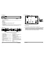
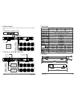
1. Loop Outputs 1 & 2
Unbalanced mono RCA connections for sending
audio to other equipment.
2. Unbalanced Inputs 1&2
Unbalanced mono RCA input connections for
connection of sources.
3. Balanced Inputs 1 & 2
Set-screw connections for sources with balanced
output.
4. Input Level Adjustment Dials
Attenuate input volume levels. Turn counter-
clockwise to decrease and clockwise to increase
the level.
5. Speaker Output Connections
Set-screw connections for speaker output
channels 1 & 2. Accommodates 22-12AWG
wire.
6. Master Power Switch
Rocker switch to control master power state.
Must remain “On” during amplifier use.
7. IEC Power Cord
Detachable power for amplifier.
8. Power Mode Selector Switch
Set the amplifier for control via the front power
button (ON), 12V trigger (TRIGGER DC 12V), or
audio sense (AUTO).
9. 12 Volt Trigger Loop In and Out
When 4.5-15 Volts DC are applied to Loop In,
amplifier will turn on. When voltage is dropped,
amplifier turns back off. Loop out allows other
equipment to be controlled from the same 12 volt
signal.
10. AC Fuse
Replaceable main power fuse.
P
OW
ER
2
1
PR
O
T
-
20
-
10
C
L
I
P
-
30
E
C
A
-7
0A
M
P
-
2D
-
300A
1
2
3
1. Power Switch with LED Indicator
Momentary switch for manual control of standby power mode. Only functions when the power mode is
set to “ON”.
BLUE
– On.
RED
– Standby.
2. Protection LED
Indicates whether a channel is operating correctly or is in protection.
BLUE – Normal.
RED – Protection. (Indicates an issue with installation or setup)
3. Output Level Meter
Level meter flashes green to indicate current output level for each channel. LEDs will illuminate green
accordingly as levels ranging from -30dB to -10dB are played. If a channel is clipping, the red CLIP LED
will illuminate during periods of clipping (turn down input level immediately if clipping occurs).
6. Front Panel
7. Rear Panel
Note: ECA-70AMP-2D-300A shown. All models share this layout, but have different specs for Power and Fuse ratings.
OUT
IN
ON
POWER
MODE
LOOP OUT
LEVEL
OUTPUTS
0V 0V
70V
70V
OF
ONLY
CAUTION:
TYPE.
ATTENTION:
INPUTS
CH1
CH2
CH2
CH2
CH1
CH1
CH2
CH1
ON
OFF
MASTER
POWER
FUSE TYPE:
T4AL 250V
T8AL 250V
115/230V
VOLTAGE
SWITCH
COMMERCIAL
AUDIO
EQUIPMENT
E330247
AUDIO
1
2
3
4
5
6
7
9
10
8
*Terminals marked with are hazardous live and external wiring connected to these terminals requires
installation by an instructed person or the use of ready-made leads or cords.
1. Input Voltage Switch
Set the input voltage for 115V or 230VAC operation based on the voltage available.
Note:
The ECA-70AMP-2D includes an IEC cable meant for use with a NEMA 5-15 receptacle supplying
115V AC power. For countries utilizing 230V AC power, the cable can be swapped to the correct
cable for that region. When using the 230V AC input voltage setting, change the fuse in the
amplifier from the included to a fuse rated for 230V AC. See the Specifications on page <Speci
-
fications> for the correct fuse type for each model. Using the wrong fuse could result in blown
fuses or damage to the amplifier, which is not covered by the warranty.
8. Bottom Panel
INPUT
VOLTAGE
51
1
INPUT
VOLTAGE
51
1
1

