EPC EPC9147C Quick Start Manual Download Page 5

QUICK START GUIDE

EPC9147C Motor Drive Controller Interface Board 

EPC – POWER CONVERSION TECHNOLOGY LEADER   |   

EPC-CO.COM

   |   ©2021   | 


|    5

Compatible Motor Drive Inverters 

A list of motor drive inverter power boards compatible to the EPC9147C is given in table 2.

EPC9147C Electrical Specifications 

Table 2: Compatible eGaN FET/IC motor driver inverters to the EPC9147C 

Motor Drive Inverter Board Number

Basic Specifications

Web Link

EPC9146 Rev. 2.1

400 W, 3-phase BLDC Inverter using EPC2152

EPC9146 – 400 W Motor drive demo board

EPC9145 Rev. 1.1

1000 W, 3-phase BLDC Inverter using EPC2206

EPC9145 – 1000 W Motor drive demo board

Table 3: Electrical Specifications (T

A

 = 25°C) EPC9147C

Symbol

Parameter

Conditions

Min

Nominal

Max

Units

V

3.3EXT

External 3.3 V Operating voltage 

J7 is not mounted

3.1

3.3

3.5

V

V

5VEXT

External 5 V straight to ST board connector

4.9

5.0

5.1

V

Table 4: Motor interface connection (J2) pin allocation map

Pin #

Pin Name

Pin #

2

PWMH1

GND

1

4

PWML1

GND

3

6

PWMH2

GND

5

8

PWML2

GND

7

10

PWMH3

3V3

9

12

PWML3

3V3

11

14

EncA

3V3

13

Index

18

EncB

GND

17

20

EncI

GND

19

22

Vin

GND

21

24

V1

GND

23

26

V2

GND

25

28

V3

GND

27

30

Iin

GND

29

32

I1

GND

31

34

I2

GND

33

36

I3

GND

35

38

EN/Pgood

LEDerr

37

40

Tsns

LEDact

39

CONNECTION DETAILS 

Inverter 

A 40 pin connector is used to interface power, PWM signals and analog 
feedback signals between the interface board and the motor drive 
inverter. Table 4 gives the map (J2) for each signal

PROGRAMMING

The ST Nucleo board that is connected to the EPC9147C board provides 
a full programmer and debugger onboard. The user can program the 
ST Nucleo board by using a USB cable connected to connector CN1 to 
the ST Nucleo board and by using official ST integrated development 
environment.
More details on the ST environment can be found at this page:  

https://www.st.com/ content/st_com/en/ecosystems/stm32-motor-
control-ecosystem.html

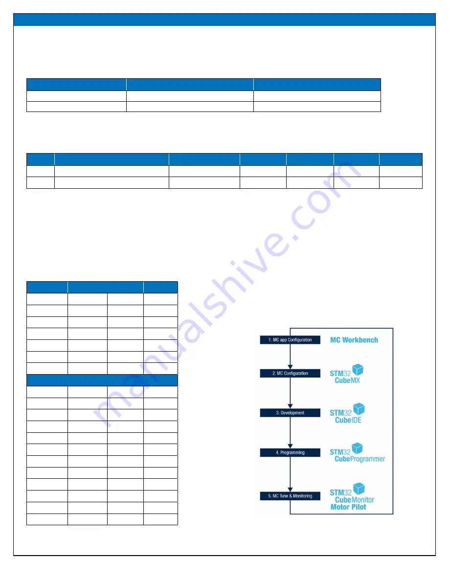
The flow, as described by ST, can be depicted in Figure 4.

Figure 4 - ST motor control development programs

Summary of Contents for EPC9147C

Page 1: ...Revision 2 2 Development Board EPC9147C Quick Start Guide MotorDriveControllerInterfaceBoard STMicroelectronicsSTM32Nucleo...

Page 2: ...istingSTMicroelectronics Integrated Development Environment resources to program the controller board that controls a motor powered by an eGaN FET IC 3 phase inverter using sensor less field oriented...

Page 3: ...in to stop the motor Speed potentiometer on EPC9147C This knob can be used to change the motor speed By default the potentiometer is not interfaced in original ST firmware so it is up to the customer...

Page 4: ...motordriveinverterdriveQSGcarefullyto determine the correct scaling factors The locations of the test points are shown in figure 1 b MonitoringJumperSettings The EPC9147C is provided with a set of jum...

Page 5: ...on J2 pin allocation map Pin Pin Name Pin 2 PWMH1 GND 1 4 PWML1 GND 3 6 PWMH2 GND 5 8 PWML2 GND 7 10 PWMH3 3V3 9 12 PWML3 3V3 11 14 EncA 3V3 13 Index 18 EncB GND 17 20 EncI GND 19 22 Vin GND 21 24 V1...

Page 6: ...eo board are mounted and that the selector on the 5V_SEL is set on 5V_STLK position Start the STM32CubeProgrammer click on Connect button by making sure that the ST LINK option is chosen Once connecte...

Page 7: ...black button once 7 Press the blue button once Motor start spinning at a fixed speed 8 Press the blue button once again Motor Stops Warning The human interface controls and knob as well as the entire...

Page 8: ...tains a file G431 EPC9145 DummyNema34_50k_100n stmcx and a directory named G431 EPC9145 DummyNema34_50k_100n Savetheseinaspecificlocationfolderinyourcomputer thenstarttheSTMotorControlWorkbenchprogram...

Page 9: ...C CO COM 2021 9 Project generation dialog box will appear Verify it matches Figure 12 s settings and then click Generate Once the Generation is complete click OpenFolder button and then click the Clos...

Page 10: ...ONVERSION TECHNOLOGY LEADER EPC CO COM 2021 10 Intheexplorerwindowwherethegeneratedcodefolderisshown asinFigure14 openthefoldernamedSTM32CubeIDE Figure 14 Generated code folder Inside the STM32CubeIDE...

Page 11: ...will enter in Debug mode Click the Terminate button as in Figure 18 and disconnect the USB cable The STM32CubeIDE program can be closed The ST Nucleo Board in the EPC9147C is now ready to run the moto...

Page 12: ...in It is now possible to move the graphic potentiometer on the GUI to change the speed of the motor and to change the motor direction Refer to ST user guide manual for more details on how to work with...

Page 13: ...SMD 1 K 0 1 1 10W 0603 Yageo RT0603BRD071KL 11 38 R2 R3 R4 R6 R7 R8 R13 R15 R19 R20 R22 R30 R32 R38 R39 R40 R41 R44 R45 R48 R49 R56 R60 R61 R64 R68 R69 R72 R84 R86 R88 R89 R92 R93 R96 R100 R104 R108 R...

Page 14: ...W R32 EMPTY 0 0 1 W R34 0 0 1 W R36 0 0 1 W R38 EMPTY 0 0 1 W R4 EMPTY 0 0 1 W R7 EMPTY 0 0 1 W R9 0 0 1 W R11 0 0 1 W R13 EMPTY 0 0 1 W R15 EMPTY 0 0 1 W R17 0 0 1 W R19 EMPTY 0 0 1 W R21 0 0 1 W R23...

Page 15: ...tiontool thisboardisnotdesignedforcompliancewiththeEuropeanUniondirectiveonelectromagneticcompatibilityoranyothersuchdirectivesorregulations Asboard buildsareattimessubjecttoproductavailability itispo...

Reviews: