background image

Eobody2HF  / Quick Start

III. Quick start

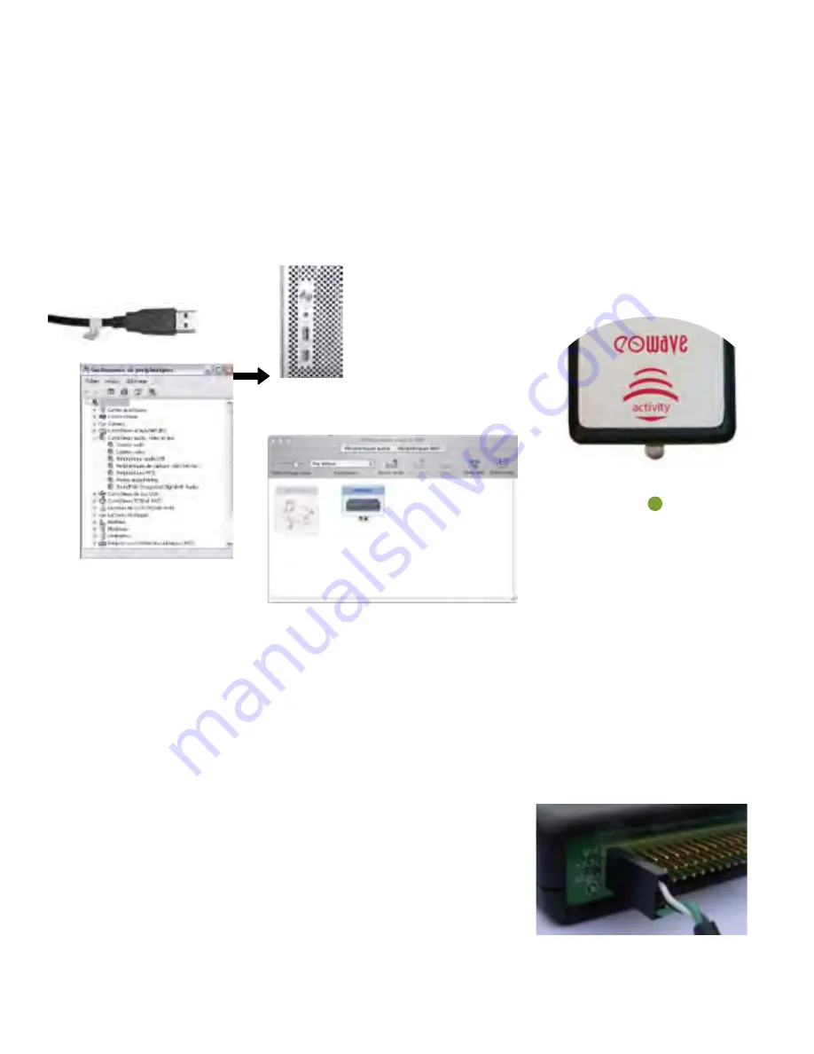
Connect the receiver to your computer 

Connect the receiver to your computer with the USB mini cable 

(or to any USB hub connected to your computer). 

You do not need any MIDI interface. 

Your Eobody2 HF will be recognized as a new audio device

 for PC, as 

Eobody2 MIDI interface with Mac

. When right connected, the receiver LED turns green.

Two or more Eobody2 HF can be connected directly to the USB inputs of your computer, but they can also be connected 

via a USB hub. When more than one Eobody2 HF are connected, they will appear like different audio peripherical with 

PCs, different Eobody2 HF MIDI interface with Mac. In this case, you will be able to rename your Eobody2 with different 

names. When the units have been named, their given name will appear. (See Global Parameters Section). Theorically, 16 

receivers may be active in the same area, but this number may be reduced depending on the area radio perturbation...

Connect a sensor to the transmitter


Eowave sensors compatible with the Eobody2HF wireless interface have a thin 3 pins connector. To connect a sensor to 
the transmitter, just plug the 3 pins connector in one of the male 3 pins connector from the transmitter. Sensors like ac-
celerometers need 2 inputs. (See sensor technical datasheets). 


Check transmission

Try a sensor. When acting a sensor, the receiver LED blinks red. It means that the receiver is receiving the datae. 

On Windows (here the French version on XP), 

your eobody2 should appear as an audio device 

in the audio /video & game device window.

On OSX it's even easier, eobody2 should 

appear in the audio & midi configuration 

panel. 

Respect the sensor polarity

Note that this is highly recommanded to connect the sensors to the transmitter 
before starting your sequencer software. Unplugging sensors while using your 
sequencer software may cause breaks during the usb data transmission which 
could lead you to restart your software. 

8

Summary of Contents for Eobody2HF Wireless

Page 1: ...Eobody2HF Wireless USB Wireless Sensor Interface The wireless solution for dancers and installations User s Manual ...

Page 2: ...y to repair the interface or the components inside of it Please contact eowave for technical support at sales eowave com Do not use your Eobody2 HF nor store it in dusty areas damp areas extreme temperatures exposed to direct sunlight areas prone to strong vibrations Do not insert any objects nor pour any liquid into the unit Protect the unit against violent shocks Never touch your Eobody2 HF nor ...

Page 3: ...lowing items Make sure everything is in the box 1 Eobody2 HF Wireless receiver 1 Eobody2 HF Wireless transmitter 1 usb mini cable 1 rechargeable battery inside the transmitter in option dance pouch additionnal arm band belt Naming things Eobody2 HF Wireless receiver this part is connected to the computer via USB The receiver receives the data from the transmitter unit Eobody2 Wireless transmitter ...

Page 4: ...mates windows garage doors Control surfaces are everywhere Faced to art control appears to be the new way of expression of this early millenium Many artists are looking for new ways of expression of conceptualizing ideas In this perspective sensors open new dimensions of expression Eobody2 is the key link between the world of analogue sensors and digital systems To the Realization An early version...

Page 5: ...ering VI Understanding the receiver LED language 10 VII Eobody2 editor 11 Open the editor Eobody2 and your computer 12 Select Eobody2 MIDI port dumpall active inputs savemen initall rereadmen Internal process editor parameters 13 Analogue Inputs Parameters window 14 Inverse status digital zoom and offset filter gate message channel Formating messages to host 17 Type CC Control Change Program Chang...

Page 6: ...free trial of Max5 on www cycling74 com This free trial will automatically install Max runtime on your computer When the 30 days trial is over Max5 runtime will remain on your computer When you have succefully installed Max5 runtime you may open Eobody2 HF editor For any questions or support concerning the installation of the editor contact info eowave com For Maxers If you are a Maxer and want to...

Page 7: ...nt by the transmitter receiver tri color LED USB I O Eobody2HF Transmitter Sensors are connected to the transmitter The sensors are plugged to the 3 pins connectors Eobody2HF Quick Overview What s What sensor 3 pins connector inputs 1 to 16 activity LED on off Battery charge via USB I O USB I O for editing settings via the editor 7 ...

Page 8: ...e same area but this number may be reduced depending on the area radio perturbation Connect a sensor to the transmitter Eowave sensors compatible with the Eobody2HF wireless interface have a thin 3 pins connector To connect a sensor to the transmitter just plug the 3 pins connector in one of the male 3 pins connector from the transmitter Sensors like ac celerometers need 2 inputs See sensor techni...

Page 9: ...have launch Max5 runtime open the Eobody2HF editor In the editor select the MIDI interface you are using in the list Eobody2HF Click on RC Channel to set the new transmission channel The following window opens Follow the instructions 1 Enter command mode by clicking on commandmode 1 2 Initialize command mode by clicking on INITCOM You get the message AT OK if not try again 3 Display active channel...

Page 10: ... battery plug the transmitter via USB to the USB I O of your computer At the first use we recommend that you charge the battery for 1 night Eobody2HF Power V Questions of power VI Understanding the Receiver LED language The receiver LED is a tri color LED Here is the color code 1 It s green When connected to the USB in of your computer the receiver LED will turn green This means that it s well con...

Page 11: ...ill be the core of your settings not the receiver The emitter must be plugged before starting the editor Open the editor One of the first thing you did when you got your Eobody2HF was to download and install the editor Refer to Register and Install section if you have not Once Max5 runtime is launched double click on the editor icon to open it The following window opens 11 ...

Page 12: ...ll light up when receiving sending mes sages 2 Dump all current parameters from Eobdy2HF memory to your com puter by clicking on dumpall 3 Adjust the analogue inputs parameters settings you need Refer to the following section for a detailled description of each feature 4 Set the number of active inputs to avoid unwanted messages and to increase the response speed 5 Click on savemem to save paramet...

Page 13: ...ou may set in the editor Eobody2 internal processing sensor in message formating bit reduction PGA analogue zoom digital zoom state on off 0 127 127 offset low pass filter 32 bits processing lag noise filtering gate analogue domain 0 5V digital domain 16 bits to host up to 32x amplifier 12 bits AD converter inverse note on note off hi low note detection parameters action on the signal path analogu...

Page 14: ...igured parameters processings have been designed considering most common sensor use and are perfectly adapted to sensor use for musical or video applications You can use Eobody2HF directly with your software sequencer without programming needs Internal processing does not use your computer cpu so you can keep more cpu resources for your apps Internal configuration can be saved inside Eobody2HF int...

Page 15: ... offset zoom max mid low off on 7 offset 127 to 127 Eobody2HF parameters 0 127 127 Digital value 12 bits MIDI data 7 bits MIDI conversion zoom setting real sensor range Offset 127 Want to stay in the 7 bit MIDI world Those two parameters digital zoom and offset specify how the real range of an analogue input can be mapped on a 7 bit MIDI value As a matter of fact a sensor does not necessarily have...

Page 16: ... depht of the signal If the analogue signal moves inside the range of the noise gate no mes sage will be sent This field enables the user to set the width of the range A large range will be very ef fective against strong noise but will make the values less sensitive to a relevant change of the analogue signal A threshold of 5 corresponds to 127 different possible values ie the analogue has to chan...

Page 17: ... the 3 most significant bits on the same MIDI channel Note on message N ON trigger hi low The analogue signal must correspond to an envelope changing with time and which has a maximum value 3 parameters need to be specified note sent higher threshold lower threshold Eobody2 analyses this envelope once the envelope has reached the higher threshold a MIDI note on message NOTE ON is generated The vel...

Page 18: ...nge type pitch bend Pitch is usu ally coded over 14 bits If the 7 bits resolution is chosen they will be mapped on the 7 most significant bits of pitch infor mation controlled by the analogue signal However since Eobody2 does 12 bits conversions internally the whole 12 bits can be mapped to take better advantage of the pitch bend message This message is used to simulate the pitch changing wheels a...

Page 19: ...VIII Sensors compatibility Sensor compatibility Eowave sensors designed for Eobody2HF have been developped to get the best results from the sensor Eowave does not warrantee the use of sensors from other brands or handmade Sensor connections compatibility If you already have some Eowave sensors with jack 6 35 connectors you may build an adapter jack 6 35 to 3 pins You can also purchase one from Eow...

Page 20: ... LSB 48 51 General Purpose 0 127 LSB Controller 1 4 52 63 Undefined 0 127 LSB 64 Damper pedal 63 off 64 on on off Sustain N Function Value 65 Portamento on off 63 off 64 on 66 Sustenuto on off 63 off 64 on 67 Soft pedal on off 63 off 64 on 68 Legato footswitch 63 off 64 on 69 Hold 2 63 off 64 on 70 Sound Controller 1 0 127 LSB Sound Variation 71 Sound Controller 2 0 127 LSB Timbre 72 Sound Control...

Page 21: ...y NOTE ON 1 127 X NOTE OFF 64 X After Touch Key o X Channel o X Pitch Bender o X 10 bit resolution Control Change 0 127 X memorised Program Change 0 127 X Program number 1 128 System Exclusive o o System Common Song Pos X X Song Sel X X Tune X X System Real time Clock X X Commands X X AUX Messages Local ON OFF X X All Notes OFF X X Active Sense X X Reset X X Mode 1 OMNI ON POLY Mode 2 OMNI ON MONO...

Page 22: ...00 meters outdoor aMeets the IEEE 802 15 4 standart General Compatible MIDI protocole Eobody Editor PC Mac IntelCore compatible Non volatile memory USB powered Receiver Input type USB 3 color activity LED Low battery LED signal Size 76 x 36 x 18 mm Transmitter Number of sensor inputs 16 per transmitter Input type socket 9V battery powered Ergonomic pouch designed for dancers Pouch size 105 x 95 x ...

Page 23: ...notice do not modify this unit This product when installed as indicated in the instructions contained in this manual is compatible with the CE norm FCC requirements 2 Important When connecting this product to accessories and or another product use only high quality shielded cables Cables supplied with this product must be used Follow all installation ins tructions Failure to follow instructions co...

Page 24: ......

Reviews: