background image

4

EN

Important notes

• 

Unprofessional installation may 

cause a fire hazard! Please read these in-
stallation instructions carefully. In particu-
lar, please observe the dimensions stated 
and the following notes.

• 

This device can be used by children aged 
8 upwards and by persons with physical, 
sensory, or mental disabilities, or who 
have inadequate experience and knowl-
edge if they are supervised or if they have 
received adequate instruction in how to 
use the device safely and understand the 
associated risks. Children may not play 
with this device. Children may not clean 
or carry out any user maintenance if un-
supervised. 

• 

Children should be supervised to make 
sure that they will not play with the unit.

• 

 Only specialists may install and con-

nect the sauna heater, control unit and 
other electrical equipment with a fixed 
mains connection. The necessary protec-
tive measures according to VDE 0100 of § 
49 DA/6 and VDE 0100 part 703/2006-2 
must be observed.

• 

Sauna heater and controller may only be 
used in sauna cabins made of suitable, 
low-resin, untreated materials (e.g. spruce).

• 

Only a sauna heater with the appropriate 
power output may be installed in the sau-
na cabin.

• 

Please provide air intake and vent open-
ings in each sauna cabin. The air intakes 
must always be positioned behind the 
sauna heater, approx. 5 to 10 cm above 
the floor. The minimum dimensions of the 
air intake and vent openings are stated in 
the table.

• 

The duct vents are always to be positioned 
offset diagonally to the sauna heater in 
the lower area of the rear sauna wall. The 
air intake and vents may not be covered. 
Please observe the sauna cabin supplier's 
instructions.

• 

Only the control units specified here-
in must be used for the operation of the 
sauna heater. This control unit must be 
positioned at an appropriate point on the 
cabin outer wall; the associated sensor 
must be positioned inside the sauna cabin 
according to the installation instructions 
included with the control unit.

• 


Caution: 

Covering the heater or an 

incorrectly filled stone container represent 
a fire hazard.

• 

The sauna heater must be visually inspect-
ed before each use (also by remote con-
trol) for a safe condition.

• 

Every time before the sauna is 

used, ensure that no objects have been 
left lying on the sauna heater.

• 


Caution:

 The high sauna heater 

Summary of Contents for THERMAT

Page 1: ...INNOVATIVE SAUNA TECH NOLOGY MADE IN GERMANY IP x4 THERMAT Sauna Heater print no 2934 4632 34 18 Installation and operation instruction EN...

Page 2: ...clearances 8 Mechanical installation and connections 8 9 Inner wiring 10 Connection example 400V 3N 10 Connection example 230V 1N 4 5 6 kW 11 Connection example 230V 1N 7 5 9 kW 12 Special advice for...

Page 3: ...shipped the goods Please note that you will only be able to achieve anoptimumsaunaclimateifthecabinwithitsair intake and ventilation the sauna heater and the control unit are aligned to each other Ple...

Page 4: ...in untreatedmaterials e g spruce Only a sauna heater with the appropriate power output may be installed in the sau na cabin Please provide air intake and vent open ings in each sauna cabin The air int...

Page 5: ...e cabin size in rela tion to the power input in kW When installing the sauna heater please ensure that the vertical clearance be tween the sauna heater upper edge and the sauna ceiling is maintained P...

Page 6: ...where the cable exits the sauna heater and guide this cable outside through the hole to the control unit The cable and all other connecting cables mains power cables and cabin lighting should be inst...

Page 7: ...on to 230V 1N AC power supply possible Power rating 4 5 kW 6 0 kW 7 5 kW 9 0 kW For sauna size 6 8 m 6 8 m 7 10 m 9 14 m Min size air inlet and exhaust vent 35 x 3 cm 35 x 4 cm 35 x 5 cm 35 x 6 cm Hei...

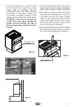
Page 8: ...g bracket over the air intake vent as shown in the Illust 2 3 and screw it onto cabin wall with the spax screws from the delivery scope Illust 2 Illust 3 Wall mounting bracket 64 cm 58 5 cm cabin wall...

Page 9: ...ver with spacer Illust 4 Terminal block Lock nut Cable gland Illust 5 3 Close the terminal box with cover using 2 fixation screws Observe that the integrated spacer faces outwards See Illust 4 for det...

Page 10: ...Hz 400 V 3 x 16 35 x 3 cm 5 x 2 5 mm 5 x 1 5 mm no Econ D series Emotec D series EmoStyle D series EmoTouch 6 0 kW 35 x 4 cm 7 5 kW 35 x 5 cm 9 0 kW 35 x 6 cm All cross sections of a line are minimum...

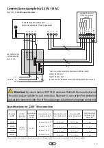
Page 11: ...se a proper fuse protection andsuitableconnectioncable Riskoffireanddamagestohardwarebyimproperconnection Power rating per DIN Electrical connection Fuse protection for control unit in A Connecting ca...

Page 12: ...nectioncable Riskoffireanddamagestohardwarebyimproperconnection Power rating per DIN Electrical connection Fuse protection for control unit in A Connecting cable mains control unit in mm Connecting ca...

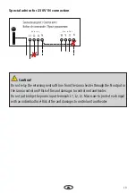
Page 13: ...sauna control unit Risk of fire and damages to control unit and heater Do not just bridge the power input terminals L1 L2 L3 Mare sure to protect each input with an individual fuse Risk of fire and d...

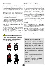
Page 14: ...daily commercial use we recommend to check the condition of sauna stones every 2 3 months and to reshuffle them By home use the sauna stones need to be checked and reshuffled at least once per year N...

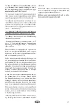
Page 15: ...other electrical units will be protected by this ELCB Under current manufacturing technology it is not reasonable to use heating elements for sau na heaters which do not collect moisture from the sur...

Page 16: ...your questions quickly and compe tently please provide the information printed on the type shield including the model item no and serial no in all inquiries Equipment commissioning date ______________...

Page 17: ...roducts is designed for the ship ping of individually packed goods pallet We expressly point out that our packaging is not suitable for individual shipments via parcel post The manufacturer shall acce...

Reviews: