background image


Doc: 
Issue 
Date 
Page 

VLT-MAN-ESO-14650-4942      
P96   
24.06.2015       
127 of 161 


ESO, Karl-Schwarzschild-Str. 2, 85748 Garching bei München, Germany 


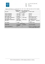
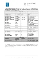
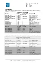
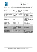
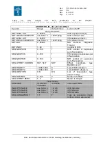
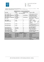
Table 25: Parameters for the template 

XSHOOTER_slt_obs_FixedSkyOffset.

It allows to alternate 

object and sky observations by couple. 

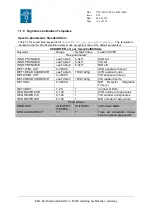
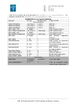
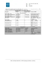
XSHOOTER_slt_obs_FixedSkyOffset 

Keyword 

Range  

Default Value 

Label in P2PP 

Free parameters 

INS.OPTI3.NAME 

see 

Table 4


1.0x11 

UVB slit  

INS.OPTI4.NAME 

see 

Table 7


0.9x11 

VIS slit  

INS.OPTI5.NAME 

see 

Table 8


0.9x11 

NIR slit 

DET1.WIN1.UIT1 

0..36000 


UVB Exposure Time (s) 

DET1.READ.CLKDESCR 

see 

Table 5


100k/1pt/hg 

UVB read-out mode 

DET2.WIN1.UIT1 

0..36000 


VIS Exposure Time (s) 

DET2.READ.CLKDESCR 

see 

Table 5


100k/1pt/hg 

VIS read-out mode 

DET3.DIT  

0.66..36000 


NIR  Detector  Integration 
Time (s) 

DET3.NDIT 

1..20 

number of DITs 

SEQ.NEXP.UVB 

0..100 

UVB  number  of  exposures 
per offset position 

SEQ.NEXP.VIS 

0..100 

VIS number of exposures per 
offset position 

SEQ.NEXP.NIR 

0..100 

NIR  number  of  exposures 
per offset position 

SEQ.FIXOFF.RA 

-100..100 

RA fixed offset (“)  

SEQ.FIXOFF.DEC 

-100..100 

DEC fixed offset (“) 

SEQ.JITTER.WIDTH 

0..2 

Jitter box width in “ 

SEQ.NABCYCLES 

0..100 

Number OS or SO cycles 

SEQ.OFFSET.ZERO 

T, F 

Return to Origin? 


Fixed Values 

INS.MODE 

SLITSPEC, 
IFUSPEC 

SLITSPEC 

Instrument Mode 

SEQ.AGSNAPSHOT 

T, F 

Take  an  acquisition  image 
before science exposures? 


Summary of Contents for P96

Page 1: ... Joël Vernet Elena Mason Name Date Signature Approved Andreas Kaufer originally approved by Sandro D Odorico Name Date Signature Released Christophe Dumas Name Date Signature European Organisation for Astronomical Research in the Southern Hemisphere Organisation Européenne pour des Recherches Astronomiques dans l Hémisphère Austral Europäische Organisation für astronomische Forschung in der südlic...

Page 2: ...Doc Issue Date Page VLT MAN ESO 14650 4942 P96 24 06 2015 2 of 161 ESO Karl Schwarzschild Str 2 85748 Garching bei München Germany ...

Page 3: ...cription of IFU centring and tracking wavelength Updated all TSF in Sec 5 Added spectrograph orientation figure Added description of Threshold Limited Integration in the NIR Added information about ghost spectra Added information about slit ifu position information in acq image header Updated limiting mags with measured NIR sensitivity and background between OH lines in VIS Updated UVB VIS NIR det...

Page 4: ...blems and status description of the current ones New items in the FAQ new calibration plan new section about the observation strategy Figures updated to be more clear and useful NIR 1 5 slit removed Intervention of July 2011 briefly described additional corrections of figures and sections according to IOT comments Very minor changes New templates added minor corrections 89 04 08 2011 30 11 2011 Mo...

Page 5: ...he overheads and optimize the integration times Calibration plan revised Phase 2 minor modifications re writing sentences new draws contacts added at the beginning already present in other pages Other minor adjustments of the tables and links 90 91 08 08 2012 No ADCs mode sect 2 2 2 updates of sects 2 4 2 24 13 1 4 15 3 1 3 4 3 5 7 5 9 Adding a new section about the observations without ADCs 2 2 2...

Page 6: ...ng the acknowledgements warning about the snapshots during the acquisitions offsets that will not be saved anymore only last snapshots end of acquisition kept warning about the exposure times of all calibration frames that will be revised warning about the wavelength calibration at night that should be performed with 2dmap template instead of ARC P92 Change of format doc to odt allowed 2dmap wave ...

Page 7: ...All CMA Merging imaging mode manual with main manual as per ESO standard Correction of some language issues obsolete sections removed or reorganized Radial velocity accuracy added telluric lines correction tool reference added updates of references and features P95 20 11 2014 Updates Sects 1 8 2 2 2 new sections 2 4 7 2 4 14 P96 26 02 2015 Homogenizing the overheads and references Adding the mappi...

Page 8: ...heric Dispersion Correctors 25 2 2 2 ADCs problems and disabled ADCs observing mode in SLIT and IFU 26 2 2 3 Detector QE curves 35 2 2 4 The UVB spectrograph 35 2 2 4 1 Slit carriage 35 2 2 4 2 Optical layout 36 2 2 4 3 Detector 37 2 2 5 The VIS spectrograph 39 2 2 5 1 Slit carriage 39 2 2 5 2 Optical layout 39 2 2 5 3 Detector 39 2 2 6 The NIR spectrograph 40 2 2 6 1 Pre slit optics and entrance ...

Page 9: ...U 76 3 4 4 Nodding along the slit SLIT only 77 3 4 5 Fixed offset to sky SLIT and IFU 78 3 4 6 Generic offset SLIT and IFU 78 3 4 7 and IFU templates 78 3 5 Observation strategy summary and tricks 79 3 5 1 Instrument setup 79 3 5 2 Observation strategy 80 3 5 3 Telluric standard stars and telluric lines correction see also Sect 6 6 1 82 3 5 4 Observing bright objects limiting magnitudes and the di...

Page 10: ...s 129 7 1 6 Night time Calibration Templates 132 Spectro photometric Standard Stars 132 Telluric standards 137 Attached night calibrations must be taken after a science template 140 Arcs multi pinhole 2d wave maps wavelength calibration 143 7 1 7 Daytime Calibration templates 145 Slit and IFU arc lamp calibrations resolution tilt 145 Flatfield pixel response orders localization 146 Format check 1s...

Page 11: ...lit width 0 5 0 8 1 0 1 3 1 6 5 0 Detector 4k x 2k E2V CCD Visual red arm Range 550 1000 nm in 14 orders Resolution 8800 0 9 slit Slit width 0 4 0 7 0 9 1 2 1 5 5 0 Detector 4k x 2k MIT LL CCD Near IR arm Range 1000 2500 nm in 16 orders Resolution 5100 0 9 slit Slit width 0 4 0 6 0 9 1 2 1 5 0 0 6 JH 0 9 JH Detector 2k x 1k Hawaii 2RG Slit length 11 SLIT or 12 6 IFU Beam separation Two high effici...

Page 12: ...summarized in Table 1 A Consortium involving institutes from Denmark Italy The Netherlands France and ESO built x shooter Name of the institutes and their respective contributions are given in Table 2 1 3 Shortcuts to most relevant facts for proposal preparation The fixed spectral format of X shooter see Table 11 on page 50 Spectral resolution as a function of slit width see Table 12 on page 52 In...

Page 13: ...em DIT Detector Integration Time ESO European Southern Observatory ETC FDR Exposure Time Calculator Final Design Review FF Flat Field GUI Graphical User Interface ICS Instrument Control Software IFU Integral Field Unit ISF Instrument Summary File IWS Instrument Workstation LCU Local Control Unit N A Not Applicable OB PAE Observing Block Preliminary Acceptance Europe P2PP Phase 2 Proposal Preparati...

Page 14: ...bration plan v1 0 XSH PLA ESO 12000 0088 2 X shooter Templates Reference Manual v0 2 XSH MAN ITA 8000 0031 3 X shooter technical note about the 11th order vignetting in K band 4 X shooter A A article Vernet et al 2011A A 536A 105V 5 Report about the non destructive NIR readout mode http www eso org sci facilities paranal instruments xshooter doc reportNDreadoutpublic pdf ...

Page 15: ... up a database of spectro photometric standards from the UV to the NIR Hamuy et al 1994PASP 106 566H Southern spectrophotometric standards 2 3 For the pipeline and data reduction Modigliani et al 2010SPIE 7737E 56M The X shooter pipeline 4 For the Reflex interface Freudling et al 2013A A 559A 96F Automated data reduction workflows for astronomy The ESO Reflex environment 5 For the imaging mode Mar...

Page 16: ...XSHOOTER will be available at UT3 instead of UT2 This would allow decreasing a bit the pressure factor on this instrument In P93 is introduced the light imaging mode of XSHOOTER performed with the acquisition and guiding camera At the same time only a single snapshot is taken of the last image during the acquisition loop 2 in case of blind offset before and after the blind offset More details will...

Page 17: ...sue Date Page VLT MAN ESO 14650 4942 P96 24 06 2015 17 of 161 ESO Karl Schwarzschild Str 2 85748 Garching bei München Germany 2 Technical description of the instrument Figure 2 Schematic overview of X shooter ...

Page 18: ...sators ADCs in the UVB and VIS arms and a warm optical box in the NIR arm The three arms are fixed format cross dispersed échelle spectrographs that operate in parallel Each one has its own slit selection device o The UV Blue spectrograph covers the 300 550 nm wavelength range with a resolving power of 5100 for a 1 slit o The Visible spectrograph covers the range 550 1000 nm with a resolving power...

Page 19: ... 6 telescope beam and a mirror slide with 3 positions that can be inserted in the telescope beam one free position for a direct feed from the telescope one mirror which reflects the light from the integrating sphere equipped with o Wavelength calibration Ar Hg Ne and Xe Penray lamps operating simultaneously o three flat field halogen lamps equipped with different balancing filters to optimize the ...

Page 20: ... send the full 1 5 1 5 field of view to the A G camera This is the position used during all acquisition sequences o spectroscopic observations and monitoring a slot lets the central 10 15 of the field go through to the spectrographs while reflecting the peripheral field to the A G camera This is the position used for all science observations o artificial star a 0 5 pinhole used for optical alignme...

Page 21: ...espect to the directly transmitted central one The measured overall efficiency of the two lateral slitlets is 85 of the direct transmission but drops to 50 below 400 nm due to reduced coating efficiency in the blue An example of an IFU standard star is showed in Figure 5 Figure 4 Top view of the effect of the IFU The central field is directly transmitted to form the central slitlet green while the...

Page 22: ...R arm Figure 5 IFU telluric standard star B type star One can note the three slices in each order of each arm The telluric absorption lines are easily visible in the VIS and NIR arms One can also note the effect of the atmospheric dispersion change of distance between the slices between blue and red orders in UVB VIS arms Blue orders Red orders Red orders Blue orders Blue orders Red orders Blue Re...

Page 23: ...rect acquisition U B V R I 22 22 22 5 22 5 22 5 30s 30s 20s 20s 20s We still have to measure their limiting magnitudes under clear conditions and in dark time However in case of worse weather the limiting magnitudes are smaller We still recommend to use blind offsets in case the object is fainter than 22 22 5 especially if the weather constraints are selected for thin thick transparency and seeing...

Page 24: ...2 2 1 6 The flexure compensation tip tilt mirrors Light reflected and or transmitted by the two dichroics reaches in each arm a folding mirror mounted on piezo tip tilt mount These mirrors are used to fold the beam and correct for backbone flexure to keep the relative alignment of the three spectrograph slits within less than 0 02 at any position of the instrument They also compensate for shifts d...

Page 25: ...633 nm for the UVB and the VIS ADCs respectively In the AUTO mode their position is updated every 60s based on information taken from the telescope database Unfortunately due to some problems affecting the ADCs they have been disabled since August 1st 2012 See the following section for more information about the observations without ADCs The NIR arm is not equipped with an ADC The NIR arm tip tilt...

Page 26: ...he situation is back to normal for the next few months Incorrect position of ADCs might lead to slit losses worse than if they are not used Consequently the ADCs were temporarily disabled set at the non deviation position as in the IFU mode on August 1st A major intervention to fix the problem is currently under investigation In the following pages you will find useful information characterizing t...

Page 27: ...ault 470nm and The dispersion effect of the atmosphere on XSHOOTER spectra depends on the tracking wavelength used by default 470nm Therefore the current effect is shown in the following plots for the UVB VIS and NIR arms Atmospheric dispersion effect no ADCs on the position of the spectrum inside different orders depending on the airmass and the arm UVB top VIS middle NIR bottom The wavelength is...

Page 28: ...rison of ADCs efficiency at different slit angle The measure was performed at relatively high airmass AM 1 8 and compares the flux between the slit position parallactic 90 degrees and parallactic angles ratio flux perpendicular flux parallactic The average value corresponds to the average of measurements for each order the range gives the min max values of the ratio and the standard deviation std ...

Page 29: ...s In this subsection a summary is presented first a modeling for narrower slits is shown in second and finally the detailed measurements corresponding to the first part are provided We consider here the ratios of the observation at 45 degrees or 90 degrees of the parallactic angle to the parallactic angle for different airmasses Summary Arm airmass Ratio 45 parall Ratio 90 parall UVB 1 10 0 98 0 8...

Page 30: ...ption will be considered for the SLIT mode as well In the following tables we compare the flux ratios other the orders for the observations at 470nm default tracking wavelength with respect to the observation at another wavelength The observations were performed without ADCs in nodding mode at AM 1 35 If the user chooses the tracking wavelength equals to 600nm instead of 470nm F470 F600 Arm Averag...

Page 31: ...ux ratio AM 1 51 AM 1 10 arm Slit angle average range std UVB Parallactic 0 89 0 43 1 0 0 16 UVB Parall 45 0 81 0 59 0 95 0 12 UVB Parall 90 0 68 0 30 1 0 0 24 VIS Parallactic 0 92 0 82 1 0 0 05 VIS Parall 45 0 81 0 70 0 98 0 09 VIS Parall 90 0 66 0 42 1 0 0 18 g Airmass constraints for observations To help in the process of observation preparation below is a plot from VIMOS MOS mode showing the a...

Page 32: ...ctic angle is not followed during the exposures but the slit is setup at the parallactic angle at the moment of the acquisition This angle is followed during the exposure It implies that the atmospheric dispersion direction will change with the time with respect to the slit angle The approximate relative evolution of the parallactic angle post meridian crossing for different hour angles is shown i...

Page 33: ...parallactic angle will change by 35 degrees In the case of declination of 30 degrees at the start of the observation the slit angle is set at 0 degree for relative reference and then in less than 1 h the atmospheric dispersion is perpendicular to the slit With the ADCs such evolution was not a problem but without ADCs one has to take this evolution into account and the airmass values its evolution...

Page 34: ... observation it is recommended to do short exposures and do some re acquisitions to setup frequently the slit at the parallactic angle If it is not performed after few minutes the main dispersion direction will imply that some orders will be missed For declination 50 degrees in 1h 1 HA the airmass will change from AM 1 12 to 1 13 therefore the dispersion for the UVB arm between the blue and red or...

Page 35: ...ser cut Invar plate manufactured with the LPKF Laser Cutter used for FORS and VIMOS It is mounted on a motorized slide in order to select one of the 9 positions available All science observation slits are 11 high and different widths from 0 5 to 5 the latter for spectro photometric calibration are offered In addition a single pinhole for spectral format check and order tracing and a 9 pinhole mask...

Page 36: ...elle grating blazed at 41 77 The off blaze angle is 0 0 while the off plane angle is 2 2 After dispersion the collimator creates an intermediate spectrum near the entrance slit where a second folding mirror has been placed This folding mirror acts also as field mirror Then a dioptric camera 4 lens groups with CaF2 or silica lenses 1 aspherical surface reimages the cross dispersed spectrum at f 2 7...

Page 37: ...or flexure measurement and engineering purposes is also implemented Measured properties and performances of this system are summarized in Table 6 The associated shutter located just after the slit is a 25mm bi stable 2 coil zero dissipation shutter from Uniblitz type BDS 25 Full transit time is 13ms Since the slit is 2 8mm high 11 at f 6 5 the illumination of the detector is homogenous within 10ms...

Page 38: ...e e rms Slow 2 5 Fast 4 5 Slow 3 1 Fast 5 2 Short DIT 25 DIT 300s 8 0 Saturation ADU 65000 65000 45000 for a single readout TLI 42000 ADUs used for long DITs Full frame readout time s 1x1 slow fast 68 16 1x2 slow fast 34 8 2x2 slow fast 17 4 1x1 slow fast 89 21 1x2 slow fast 45 11 2x2 slow fast 22 5 1 46 for a single readout Dark current level 0 2e pix h 1 1e pix h 21 e pix h Fringing amplitude 5 ...

Page 39: ...al For cross dispersion it uses a 49 Schott SF6 prism in double pass The main dispersion is achieved through a 99 4 grooves mm 54 0 blaze échelle grating The off blaze angle is 0 0 and the off plane angle is 2 0 The camera 3 lens groups 1 aspherical surface reimages the cross dispersed spectrum at f 2 8 plate scale 8 98 mm onto the detector not tilted Focusing is obtained by acting on the triplet ...

Page 40: ...high and different widths are offered from 0 4 to 5 see Table 8 Table 8 NIR spectrograph slits and calibration masks Size Purpose 0 4 11 slit SCI CAL 0 6 11 slit SCI CAL 0 9 11 slit SCI CAL 1 2 11 slit SCI CAL 5 0 11 slit CAL 0 6 11 JH slit SCI CAL 0 9 11 JH slit SCI CAL Row of 9 pinholes of 0 5 spaced at 1 4 CAL 0 5 pinhole CAL Blind SCI CAL In July 2011 during the intervention on XSHOOTER the NI...

Page 41: ...r is slightly different They are indicated in the following table 10 Table 9 NIR spectrograph slits and resolving power slit R old slit wheel R new slit wheel 0 4 11000 10500 0 6 7950 7780 0 6 JH X 7760 0 9 5700 5300 0 9 JH X 5300 1 2 3990 3890 1 5 2540 X 5 1400 IFU 8400 8300 slits with the K band blocking filter Below is the transmission curve of the K band blocking filter ...

Page 42: ...48 Garching bei München Germany Below one can see flat field frames for the slits with and without K band blocking filter ON OFF Flat field frames for the normal 0 9 NIR slit top and for the 0 9 with blocking filter bottom One can easily note that the last orders are cut by the K band blocking filter ...

Page 43: ...15 43 of 161 ESO Karl Schwarzschild Str 2 85748 Garching bei München Germany ON OFF Flat field frames for the normal 0 6 NIR slit top and for the 0 6 with blocking filter bottom One can easily note that the last orders are cut by the K band blocking filter ...

Page 44: ...ut filter The measurements were normalized to a theoretical 1 slit The RON is not included here Wavelength nm Background with filter e s pix Background without filter e s pix Reduction in Reduction factor Sky darktime e s pix 1048 0 0195 0 056 65 2 9 0 018 1238 0 027 0 10 73 3 7 0 022 1300 0 035 0 13 73 3 7 0 040 1682 0 040 0 15 73 3 8 0 050 The measurements see above table show that with the bloc...

Page 45: ...asurements at different wavelength for the slit without filter the normal color curves correspond to the measurements at different wavelength for the slit with filter A Background with 0 9 slits with without filters a For 0 9 slit with K band blocking filter Unfortunately the background is always RON limited for DIT shorter than 1000s whatever the wavelength is for this slit with filter despite a ...

Page 46: ...B Backgrounds with 0 6 slits with without filters a For 0 6 slit with K band blocking filter Unfortunately the background is always RON limited b For normal 0 6 slit without filter For this slit the background is RON limited for DIT up to 360s at wavelength 1682nm and 450s at 1300nm Then for longer DIT the background is sky limited ...

Page 47: ...ical surfaces In order to get enough cross dispersion three prisms are used in double path Prism 1 is a 35 top angle made of Infrasil prisms 2 and 3 are two 22 top angle ZnSe prisms This design provides an almost constant order separation Main dispersion is provided by a 55 grooves mm échelle grating with a blaze angle of 46 07 The off blaze angle is 0 0 while the off plane angle is 1 8 After disp...

Page 48: ...ational reasons only a limited number of DITs is offered to the user in case of exposures longer than 300s see section 3 4 1 3 Important Warning adjacent pixels can follow different regimes by using this readout mode one can follow the normal regime and its neighbor can follow and extrapolated regime if the counts reach the extrapolation threshold This may lead to bad line profile and then to affe...

Page 49: ...d NIR bottom calibration frames Strong order curvature and varying slit tilt and scale are clearly visible Note for the NIR arm the higher thermal background in longer wavelength This is specially the case in the 11 th order that corresponds to the K band Blue orders Red orders Red Blue UVB arm Blue orders Red orders Red Blue VIS arm Blue orders Red orders Blue Red NIR arm ...

Page 50: ...8 13 540 1 556 0 593 0 VIS 30 525 3 550 5 561 0 29 535 8 568 0 580 2 28 554 6 585 9 600 8 27 575 2 607 7 622 9 26 597 4 629 5 646 8 25 621 3 653 8 672 5 24 647 2 682 1 700 4 23 675 4 711 2 730 7 22 706 1 742 6 763 8 21 739 7 777 6 800 0 20 777 0 815 8 839 8 19 817 6 860 2 883 8 18 862 9 904 3 932 7 17 913 7 957 3 987 4 16 970 7 1001 6 1048 9 NIR 26 982 7 1005 8 1034 2 25 1020 5 1046 0 1076 7 24 10...

Page 51: ...x at order 30 NIR 52 4 pixels 0 21 pix at order 11 to 59 9 pixels 0 184 pix at order 26 The minimum separation between orders is 4 unbinned pixels to allow inter order background evaluation The dichroic crossover region between UVB VIS and VIS NIR is at 559 5 nm and 1024 nm respectively Between UVB and VIS the region where the combined dichroics transmit less than 80 is 556 0 563 8 nm 7 8 nm wide ...

Page 52: ... UVB and VIS The resolution and pixel sampling without binning as a function of the slit width is given in Table 12 Table 12 Resolution as a function of slit width UVB VIS NIR Slit width R Sampling pix FWHM Slit width R Sampling pix FWHM Slit width R Sampling pix FWHM 0 5 9100 3 5 0 4 17400 3 0 0 4 10500 2 2 0 8 6200 5 2 0 7 11000 4 8 0 6 7770 2 9 1 0 5100 6 3 0 9 8800 6 0 0 9 5300 4 2 1 3 4000 8 ...

Page 53: ...12 Limiting AB magnitude of X shooter per spectral bin using 2 pixels binning in the spectral direction at S N 10 in a 1 hour exposure Other parameters air mass 1 2 0 8 seeing 3 days from new moon 1 slit for UVB 0 9 slit for VIS and NIR The ESO ETC was used to compute these values The model uses overall efficiencies measured during commissioning Note that these performance estimates assume no degr...

Page 54: ... 8 466 4 21 4 860 2 19 8 1867 86 16 6 438 8 21 4 815 8 20 1743 33 19 414 5 21 4 777 6 20 1 1634 38 19 1 393 2 21 742 6 20 2 1538 23 19 2 373 5 20 711 2 20 2 1452 78 19 356 1 19 5 682 1 20 3 1376 31 18 339 8 19 2 653 8 20 1 1307 5 19 4 325 19 629 5 20 2 1245 24 19 5 312 2 18 607 7 20 2 1188 64 19 6 585 9 20 2 1136 96 19 2 568 20 2 1089 58 19 6 550 5 18 5 1046 19 6 1005 77 18 7 Table giving the limi...

Page 55: ...s and certainly affect the nighttime observations which follow the long exposures For this reason starting from P86 the DIT 1800s is no longer offered Remnants due to the thermal background in the reddest order of the K band has been observed occasionally also with shorter DIT This is currently under discussion and analysis However starting with P90 the DIT of 1800s will be offered again under str...

Page 56: ...w that the detector does not have remnants after arc exposures of 6 to 300s with the 1x1 binning and the normal readout mode 3s exposure in the 1x2 binning for the normal readout mode and 1s exposure for the 2x2 binning in the normal readout mode However it was observed some remnants after the observation during 300s of a very bright star that saturated the UVB detector ...

Page 57: ... positive x it moves in and becomes particularly noticeable in the dichroic cut off region between UVB and VIS arms It is strongest in the last order of the UVB spectrum in the wavelength range of the dichroic reflectivity cut off see Figure 13 left In the VIS the ghost is noticeable in several orders and its intensity is 0 5 of the parent spectrum see Figure 13 right It is particularly relevant w...

Page 58: ...t of the VIS 4 unbinned pixels Therefore whenever a good inter order background subtraction by the pipeline is important we recommend not using the 2x2 binning mode 2 4 6 NIR frames with the K band blocking filter features There is a leak in the K band blocking filters implying that one can see in the right top corner some light However this light count is much lower than without the filter and in...

Page 59: ... Germany With the 0 6 JH slit some low level interferences are visible in the reddest part of the last order The fringe peak to peak difference accounts for 10 of the level in the worse case They are due to the filter itself However they look stable over the different positions and could be corrected through the flat fields ...

Page 60: ...cial signals with a count level close to the sky background level This is mostly noticeable in the case of observations with the K band blocking filter 2 4 8 Instrument stability 2 4 8 1 Backbone flexures The active flexure compensation AFC allows to maintain the three slits aligned with respect to the reference A G pinhole to within 0 02 in both at any rotation angle for ZD 60 It is advised to ru...

Page 61: ...der by a factor of 10 and is due to a bad design of the mask located in front of the NIR array The same effect is present in the blue part of the 10th order Figure 15 NIR11th order vignetting corresponding to a flux decrease arrow Figure from L Christensen technical note Trying to correct this vignetting would imply a major operation on the NIR arm with possible risks to degrade much more the NIR ...

Page 62: ...to its readout noise In addition the fast readout mode of the VIS CCD shows also very low level pattern with a deviation from the background level of 1 Figures are available at http www eso org observing dfo quality XSHOOTER qc problems problems_xshooter html In the slow readout mode the pick up noise is lower and the patterns are not seen 2 4 12 NIR IFU parasitic reflections In the IFU mode some ...

Page 63: ...fting leading to a drift of those reference positions This is now monitored and rectified when the drift reaches a significant amount possibly leading to flux losses for the narrower slits Unfortunately a bad software update may have generated losses during the period 12 2013 06 2014 for the observations using narrow slits and the U band acquisition filter 2 4 15 TCCD features The cooling system o...

Page 64: ...tion 2 2 2 for indications about the effects of this wavelength choice on the spectrum flux depending on the orders In both spectroscopic observing modes one of the detector readout modes given in section 0 and 2 2 5 can be selected for the UVB and the VIS arm independently The readout mode is fixed for the NIR arm In IMAGING mode only the acquisition and guiding camera is used with the filters ch...

Page 65: ...ected in real time from effects of atmospheric refraction between the wavelength of the selected acquisition filter and the telescope tracking wavelength 470 nm for SLIT mode user selected for IFU observations In the coming period P93 a snapshot will only be taken at the end of the acquisition process for a direct acquisition and in case of blind offset a snapshot will be taken before and after th...

Page 66: ...t must be clearly indicated on the finding chart It is important to note that the offsets in all templates are offsets on sky as in other Paranal instruments They are computed as follows the offset RA corresponds to delta RA xcos DEC and the offset DEC is the difference delta DEC It is also important to take into account the proper motions of the objects For the reference acquisition star it has t...

Page 67: ...preparations acquisitions with p2pp3 Note that in SM our USD colleagues will help you in case of questions regarding the preparation of the OBs In VM there is a support from the astronomers at Paranal 3 3 1 Direct acquisition VLT guide star Choose the acquisition template Slit position angle 9999 parallactic angle Choose filter integration time of TCCD ...

Page 68: ...Doc Issue Date Page VLT MAN ESO 14650 4942 P96 24 06 2015 68 of 161 ESO Karl Schwarzschild Str 2 85748 Garching bei München Germany Science template added here nodding ...

Page 69: ...ESO Karl Schwarzschild Str 2 85748 Garching bei München Germany Informations of the science target in case of direct acquisition coordinates RA DEC equinox epoch proper motions in RA and DEC in arcsec year differential velocities in RA and DEC in s if any moving targets ...

Page 70: ...MAN ESO 14650 4942 P96 24 06 2015 70 of 161 ESO Karl Schwarzschild Str 2 85748 Garching bei München Germany The following snapshots are valid for both direct and blind offset OBs Specify the constraints Transparency seeing etc ...

Page 71: ...VLT MAN ESO 14650 4942 P96 24 06 2015 71 of 161 ESO Karl Schwarzschild Str 2 85748 Garching bei München Germany If needed in case of time critical observation add a constraint in the time interval range of dates and times ...

Page 72: ...VLT MAN ESO 14650 4942 P96 24 06 2015 72 of 161 ESO Karl Schwarzschild Str 2 85748 Garching bei München Germany Only if actually needed you can also define a range of valid sidereal times for the observation of your target ...

Page 73: ...s They are computed as follows the offset RA corresponds to delta RA xcos DEC and the offset DEC is the difference delta DEC BLIND OFFSET ACQUISITION Specify here in arcsec the blind offsets from the reference acquisition star to the science target Here movements from the acquisition star of 35 6 to the west and 20 5 to the north Positive value in RA moves the slit to the east Positive value in DE...

Page 74: ...Doc Issue Date Page VLT MAN ESO 14650 4942 P96 24 06 2015 74 of 161 ESO Karl Schwarzschild Str 2 85748 Garching bei München Germany ...

Page 75: ...DCs come after the IFU in the light path and are set to their OFF position where they do not disperse light The user has to choose which wavelength will be kept fixed at the centre of the IFU during observations using the SEQ IFU WLGT parameter in the XSHOOTER_ifu_acq template It is set to the middle of the atmospheric dispersion range 470nm by default Users are therefore recommended to orient the...

Page 76: ...each arm the user chooses the exposure time and the number of exposures Exposures are completely asynchronous i e in each arm whenever an exposure is finished the next one starts immediately independently of what is happening with the other arms 3 4 3 Staring synchronized SLIT and IFU Whenever exposures in the three arms have to be parallel the templates XSHOOTER_slt_obs_StareSynchro or XSHOOTER_i...

Page 77: ... of the two jitter boxes inside the slit see Figure 17 Ditto for the jittering box the jitter value corresponds to the size of the box One cycle is a pair of AB or BA observations Cycles are repeated in ABBA sequences For each arm the user chooses the number of exposures at each position and the exposure time both identical for all A and B positions Exposures are asynchronous Note that nodding is ...

Page 78: ...ding a list of cumulative telescope offsets This is particularly useful in case one wants to map an object with several slit or IFU positons The number of exposures taken at each position and the exposure time both identical at all positions have to be defined Exposures are asynchronous See also Orientation and conventions However the number of sky and object positions must be the same This is as ...

Page 79: ...n dest UVB 0 5 0 8 1 0 1 3 1 6 5 VIS 0 4 0 7 0 9 1 2 1 5 5 NIR 0 4 0 6 0 9 1 2 5 blind 0 6 JH 0 9 JH 9999 parallactic angle or choose another value NODDING FIXED OFFSET GENERIC OFFSET SYNCHRONIZED ETC IFU RRM or normal STARE UVB 100k 1x1 UVB 100k 1x2 UVB 100k 2x2 UVB 400k 1x1 UVB 400k 1x2 UVB 400k 2x2 VIS 100k 1x1 VIS 100k 1x2 VIS 100k 2x2 VIS 400k 1x1 VIS 400k 1x2 VIS 400k 2x2 NIR non dest IFU 1 ...

Page 80: ...mode corresponds to the usual observing mode with other optical instrument as UVES Select a slit of about 0 9 1 if you want to match the slit with the median seeing at Paranal 0 8 However if you are interesting in the resolving power select narrower slit At the opposite if you are interesting in the flux calibration select the 5 slits As shown in the example above you can combine in the same OB di...

Page 81: ...ou are able to do a mapping of the environment and also do offset to sky position However in the GENERIC OFFSET template all the offset values are cumulative and refer to the current position see also Sect 7 1 1 With both templates the number of exposures on sky and object must be the same This is the same for the exposure times The MAPPING templates are not restricted with respect to the number o...

Page 82: ...lluric standard stars with slits of 5 Up to P90 for saving time by default in service mode the telluric standard stars are observed in IFU or SLIT stare mode If the users need other kind of observations they should indicate it in the README or better supply their own OBs The Observatory already spend about 10 of the available time for taking telluric standard stars spectra a change from stare to n...

Page 83: ...It allows to observe ultra bright targets down to magnitude 4 It opens new windows on well known objects but still without spectra especially in the infrared due to their brightness A report as well as the reduced data obtained during the tests is available at http www eso org sci facilities paranal instruments xshooter news html It is not yet decided whether this mode will be offered to the commu...

Page 84: ...agnitudes of transient objects such as GRB counterparts supernovae and variable objects e g stellar binaries and stars with exoplanets With the implementation of the imaging mode in P93 only one acquisition snapshot is saved and not after each applied offset as was previously the case For direct target acquisition one snapshot will be saved once the acquisition process is finished In case of a tar...

Page 85: ...re recommended to take a series of 2 to 3 images per position filter exposure time The example Antenna galaxy B filter 5s exposure time below illustrates this effect of the Pelletier cooling delay More details appear in the second exposure while the seeing did not vary First exposure of the series The bkg is at 1800 ADUs and the RMS at 12 ADUs Second exposure the bkg is now at 1711 ADUs and the RM...

Page 86: ...w 13μmx13μm 0 1744 0 0016 since P92 at UT3 1 5 x1 5 but filters do not cover the corners Gain e ADU 1 29 0 02 Readout noise e rms 4 14 0 08 Saturation ADU 65535 Readout mode and overheads Fast readout mode only Wipe time 0 01 s readout time 0 33 s transfer time 0 78 s total time 1 12 s Dark current level ADU pixel h 0 97 exposure time of 10s Fringing amplitude Depends on the filters 2 to 4 in I z ...

Page 87: ...of short exposure times when the image sampling frequency corresponds to the frequency of the temperature oscillations this leads to beats and background level variations from one image to the next These variations in background level disappear if a longer exposure time is selected However they do not affect the acquisition performance In June 2011 the noise was improved and the quality of images ...

Page 88: ...Doc Issue Date Page VLT MAN ESO 14650 4942 P96 24 06 2015 88 of 161 ESO Karl Schwarzschild Str 2 85748 Garching bei München Germany Figure 3 A G camera filter curves ...

Page 89: ... 27 13 26 73 ZP XSHOOTER 11 2013 at UT3 from P92 24 83 27 91 27 83 27 74 27 36 ZP XSHOOTER 07 2011 at UT2 till P91 24 95 27 74 27 63 27 83 27 49 ZP FORS2 2011 24 31 27 68 28 09 28 32 27 67 Note The A G CCD zeropoints were determined for the Johnson filters under photometric condition The accuracy of the ZP X shooter magnitudes is about 0 05 0 1 magnitude depending on the filters FORS2 zeropoints a...

Page 90: ...lity at medium term was checked with the evolution of the bias and readout noise levels They are shown below Over a period of 52 days the RMS of the bias level variability is 0 33 and for the RON it is 0 56 c the long term stability of the instrument was tested with the spectrophotometric standard star EG274 observed during a period of more than 500 days However the star was quite often observed u...

Page 91: ...ull Moon seeing about 0 7 Table 4bis Recommended exposure times for the A G CCD S N 5 V mag 6 7 16 20 23 24 Exposure time s 0 001 0 005 1 5 60 120 180 b Observing strategies Two science templates are offered 1 XSHOOTER_img_obs STARE mode observation i e the object stays on the same detector pixel 2 XSHOOTER_img_obs_GenericOffset GENERIC OFFSET mode observations i e mapping or jittering around the ...

Page 92: ... Night zeropoints XSHOOTER_img_obs_cal_phot once per year or user provided Night distortion map XSHOOTER_img_obs_cal_dist once per year or user provided The count levels of the twilight flats should be between 10000 and 55000 ADUs In P93 they will be taken pointing to empty sky positions while until P92 they are taken at the zenith thus star traces may be possible d Quality control Some health che...

Page 93: ...of 161 ESO Karl Schwarzschild Str 2 85748 Garching bei München Germany Distortion map fringes and astrometric accuracy Figure 5bis shows the distortion maps of the TCCD with respect to the 2MASS astrometry Fig 6bis Figure 5bis UBVRI distortion maps magnified x20 ...

Page 94: ...P96 24 06 2015 94 of 161 ESO Karl Schwarzschild Str 2 85748 Garching bei München Germany Fig 6bis Distributions in RA and DEC of the difference between 2MASS and the AGCCD astrometry The difference between 2MASS and the A G CCD astrometry is 0 1 ...

Page 95: ... 85748 Garching bei München Germany The Fringing maps were obtained with skyflats The most affected filters are the r i z I The amplitude peak to peak ranges from 2 in the r to 4 in the z filter Fig 7bis Fringing maps in r and z The cuts in the bottom show the amplitude peak to peak of the fringes ...

Page 96: ...85748 Garching bei München Germany Calibration frames overview and examples Figure 8bis Three color BVI image of a galaxy with a supernova left and of a small field of 47Tuc right Observations were performed in stare mode More examples are shown in the Messenger article of the XSHOOTER imaging mode ...

Page 97: ...Doc Issue Date Page VLT MAN ESO 14650 4942 P96 24 06 2015 97 of 161 ESO Karl Schwarzschild Str 2 85748 Garching bei München Germany Figure 9bis Example of calibration images ...

Page 98: ...the photometry Pipeline support will be provided for the detector linearity determination only Below are some basic guidelines of imaging data reduction with IRAF and the swarp software 0 Preliminary steps Inspect the images reject the flat fields with too many stars or star traces Create files listing the frames per type Make sure to use darks and flat fields with the same integration times 1 Cre...

Page 99: ...ield Use the imarith task 5 Stack the science images WCS based use swarp It is possible to use the IRAF tasks imstack or imcombine to combine the science images However it has been shown that IRAF does not always properly handle large images or the WCS Therefore we recommend to use the swarp software from astromatic ex TERAPIX from E Bertin http www astromatic net software swarp Syntax swarp liste...

Page 100: ...will be modified if some imaging is introduced in the OB after commissioning all the values will be published However from the preliminary tests the readout of the AG camera is fast less than 1s the change of filter takes less than 20s and the instrument setup depends from which mode the instrument goes to the imaging mode In case of IFU it takes about 45s In slit mode it takes lass than 10s a Acq...

Page 101: ...60 469s Integration time of 180s XSHOOTER_slt_acq setup 1025 30 1055s XSHOOTER_ifu_acq setup 1025 60 1085s In addition to these times wiping time of the detector 6 1s has to be taken into account and the readout times c Delay before start of exposures In addition there is a delay of 5 s before the start of the VIS exposure and a delay of 10 s before the start of the NIR exposure d Readout overhead...

Page 102: ... readout time of the VIS arm 257s corresponding to 100s of integration time and 157s of readout time To optimize this time then one can do UVB exposure of 100s the readout time is here of 68s therefore the VIS arm can still integrate during 68s more One solution could be to do UVB exposure of 100s VIS exposure of 168s Then the execution time will be VIS exposure time of 168s readout time of VIS ar...

Page 103: ...rent exposure times and their number readout times the acquisition time and the instrument setups Note that there is an extra 5s time between the moment of the UVB VIS arms setup is done and the NIR one is done In P90 an algorithm providing indications about the optimization of the overheads was included We kindly ask the users to report potential improvements or incorrectness of this algorithm ...

Page 104: ...first guess disp solution FMCK Flat single pinhole b 1 D2 lamp 1 Halo lamp 1 1 ON OFF Every 2 days Pipeline calibration order localization ORDERDEF 1x1 binning in UVB VIS Arcs multi pinhole Th Ar or Ar Xe Hg Kr 1 1 1 ON OFF Every 2 days Wavelength and spatial scale determination calibration WAVE Arcs through slit IFU Th Ar or Ar Xe Hg Kr 1 setting 1 setting 1 ON OFF setting daily Wavelength shift ...

Page 105: ...d Triggered calibrations DIT NDIT DIT NDIT N exposures 300s 2 DIT 1 3 300s 3 DIT 3 1 300s 2 DIT 1 3 300s 3 DIT 3 1 In case the science frames use a combination DITxNDIT corresponding to the monitoring darks or to other science standard frames the darks are not duplicated There is not anymore a difference SM or VM b Now only the 1x1 binning is taken in the UVB VIS Other binning ORDERDEF are taken u...

Page 106: ...etector monitoring LINEARITY_VIS_400k Set of detector FF biases monthly detector monitoring LINEARITY_UVB_100k_1x2 Set of detector FF biases monthly detector monitoring LINEARITY_UVB_400k_1x2 Set of detector FF biases monthly detector monitoring LINEARITY_VIS_100k_1x2 Set of detector FF biases monthly detector monitoring LINEARITY_VIS_400k_1x2 Set of detector FF biases monthly detector monitoring ...

Page 107: ...n Figure 18 The templates used for this calibration is XSHOOTER_slt_cal_UvbVisArcsMultiplePinhole and XSHOOTER_slt_cal_NIRArcsMultiplePinhole The accuracy of the wavelength calibration typically achieved using the X shooter Data Reduction Software is better than 2km s over the whole wavelength range see section 2 4 9 In this process the quality of the list of lines used to perform the calibration ...

Page 108: ... in UVB 1 in VIS and ON OFF in NIR that have to be taken sequentially Flatfield templates are XSHOOTER_slt_cal_UVBLowLampFlat UVB deuterium D2 lamp flat XSHOOTER_slt_cal_UVBHighLampFlat UVB halogen lamp flat XSHOOTER_slt_cal_VISLampFlat XSHOOTER_slt_cal_NIRLampFlat And their equivalent for IFU flatfield named XSHOOTER_ifu_cal_ LampFlat Note that low frequency fringes with peak to valley amplitudes...

Page 109: ...ild Str 2 85748 Garching bei München Germany 6 4 Spectroscopic skyflats It is now possible to request the support astronomers to take spectroscopic skyflats both slit and IFU modes They will be taken on the best effort basis The performed tests show that the slits are uniformly illuminated ...

Page 110: ...ll use the setup of the instrument performed by the science template Therefore if one needs to bracket the observations by attached flat fields he she needs to create an OB like this Acquisition template dummy exposures in a science template for instrument setup attached calibration here flat fields normal observation with the science template attached calibration If one does directly the attached...

Page 111: ... your program or to specify in the readme file of your program what kind of telluric star is needed Currently the telluric standard stars observed by the Observatory should have about 10000 ADUs in the middle of the brightest orders of each arms S N 50 100 The Observatory does not provide observations of telluric standard stars with 5 slits If this S N is not enough for the purpose of your program...

Page 112: ...undertaken as an ESO Observatory Programme PID 278 D 5008 to extend to the near IR a subset of 12 standard stars from the two references cited above to the near IR Tabulated fluxes used by the pipeline for those 12 stars from 300 to 2500 nm allow an absolute flux calibration to the 5 10 Details of this programme can be found in Vernet et al Proc SPIE 7016 2008 available on the X shooter web pages ...

Page 113: ...n where the spectra have to be located and treated For example in case of 2 objects inside the slit the extraction can be performed for both objects using different boxes of research 3D reconstructed data cubes will be produced for IFU data Additional products to verify the quality of the results and a set of Quality Control parameters instrument health check and trend analysis Some of the functio...

Page 114: ...ity control plots at http www eso org observing dfo quality XSHOOTER reports HEALTH trend_report_BIAS_U VB_med_master_HC html Is it possible to do pre imaging for astrometric and photometric purposes with the AG technical CCD OBSOLETE with the release of the imaging mode Not yet even if It was successfully used during VM runs for preparing the OBs for blind offsets or to investigate better the fie...

Page 115: ...How can I find the slit object position in the acquisition image FITS header keywords HIERARCH ESO SEQ AG XCEN and YCEN record the location of the centre of the SLIT or IFU in the image Which airmass should I specify for the IFU observations Because the ADCs are not used in IFU mode one should consider not to use a large airmass Typically the airmass should be better than 1 5 However the tip tilt ...

Page 116: ...s all X shooter data is minus the position angle of the slit on the sky Note that the value 9999 can be used to set the position angle to the parallactic angle Note also that the parallactic angle is that at the time of the preset acquisition The slit is not maintained at the parallactic angle during the science exposure Offsets are always given in arc seconds but the reference system can be chose...

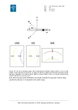
Page 117: ...sition in the slit and position on the spectrum for each arm An object at positive x black star top panel produces spectra placed as illustrated in the bottom panels NOTE a positive offset in the x or y direction will move the object in direction of x and y axis Note that the keyword ADA POSANG in the header indicates the opposite of the slit angle specified by the user It corresponds to the rotat...

Page 118: ...ollowed during the exposure the system uses the parallactic angle at the start of the OB If another PA is defined the telescope will follow this angle on sky h Examples of position angles If the user needs a position angle of 45 degrees it is just needed to enter 45 degrees in the acquisition template If the user needs a position angle of 315 degrees it is needed to enter in the acquisition templa...

Page 119: ... The first example with PA 0 degree shows the results of a positive offset in x The object star moves in the direction of the x axis and the slit moves in the x axis The x y axis are attached to the slit The second offset with PA 45 degrees shows a positive offset in y axis The Moon goes to the upper right corner movement in y axis while the slit moves in the lower left corner reverse movement in ...

Page 120: ...0 3000 2000 Equinox TEL TARG PMA 10 0 10 0 0 0 RA proper motion yr TEL TARG PMD 10 0 10 0 0 0 DEC proper motion yr TEL TARG EPOCH 1950 2000 2000 Epoch TEL TARG ADDVELALPHA 0 0 RA differential tracking velocity s TEL TARG ADDVELDELTA 0 0 DEC differential tracking velocity s TEL TARG OFFSETALPHA 36000 36000 0 0 RA blind offset TEL TARG OFFSETDELTA 36000 36000 0 0 DEC blind offset TEL ROT OFFANGLE 17...

Page 121: ...ELTA 0 0 DEC differential tracking velocity s TEL TARG OFFSETALPHA 36000 36000 0 0 RA blind offset TEL TARG OFFSETDELTA 36000 36000 0 0 DEC blind offset TEL ROT OFFANGLE 179 99 179 99 9999 9999 Slit position angle on Sky 9999 for parallactic angle INS FILT1 NAME u g r i z U B V R I A G filter DET4 WIN1 UIT1 0 36000 TCCD exposure time TEL AG GUIDESTAR CATALOGUE SETUPFILE NONE CATALOGUE Telescope gu...

Page 122: ...FFSETALPHA 0 0 RA blind offset TEL TARG OFFSETDELTA 0 0 DEC blind offset TEL ROT OFFANGLE 179 99 179 99 9999 9999 IFU position angle on Sky 9999 for parallactic angle INS FILT1 NAME u g r i z U B V R I A G filter DET4 WIN1 UIT1 0 36000 TCCD exposure time SEQ IFU WLGT 300 2000 470 Wavelength for target centring and tracking TEL AG GUIDESTAR CATALOGUE SETUPFILE NONE CATALOGUE Telescope guide star se...

Page 123: ...ditional velocity DEC in s TEL TARG OFFSETALPHA 0 0 RA blind offset TEL TARG OFFSETDELTA 0 0 DEC blind offset TEL ROT OFFANGLE 179 99 179 99 9999 9999 IFU position angle on Sky 9999 for parallactic angle INS FILT1 NAME u g r i z U B V R I A G filter DET4 WIN1 UIT1 0 36000 TCCD exposure time SEQ IFU WLGT 300 2000 470 Wavelength for target centring and tracking TEL AG GUIDESTAR CATALOGUE SETUPFILE N...

Page 124: ...ce templates Slit observations The SEQ AGSNAPSHOT is not available because a snapshot of the A G camera is saved at the end of the acquisition Table 22 Parameters for stare mode observations with the template XSHOOTER_slt_obs_Stare XSHOOTER_slt_obs_Stare Keyword Range Default Value Label in P2PP Free parameters INS OPTI3 NAME see Table 4 1 0x11 UVB slit INS OPTI4 NAME see Table 7 0 9x11 VIS slit I...

Page 125: ...I3 NAME see Table 4 1 0x11 UVB slit INS OPTI4 NAME see Table 7 0 9x11 VIS slit INS OPTI5 NAME see Table 8 0 9x11 NIR slit DET1 WIN1 UIT1 0 36000 UVB exposure time s DET1 READ CLKDESCR see Table 5 100k 1pt hg UVB readout mode DET2 WIN1 UIT1 0 36000 VIS exposure time s DET2 READ CLKDESCR see Table 5 100k 1pt hg VIS readout mode DET3 DIT 0 66 36000 NIR Detector Integration Time s DET3 NDIT 1 9999 1 n...

Page 126: ... UIT1 0 36000 UVB exposure time s DET1 READ CLKDESCR see Table 5 100k 1pt hg UVB readout mode DET2 WIN1 UIT1 0 36000 VIS exposure time s DET2 READ CLKDESCR see Table 5 100k 1pt hg VIS readout mode DET3 DIT 0 36000 NIR Detector Integration Time s DET3 NDIT 1 9999 1 Number of DITs SEQ NEXP UVB 0 100 1 UVB number of exposures per offset position SEQ NEXP VIS 0 100 1 VIS number of exposures per offset...

Page 127: ...100k 1pt hg UVB read out mode DET2 WIN1 UIT1 0 36000 VIS Exposure Time s DET2 READ CLKDESCR see Table 5 100k 1pt hg VIS read out mode DET3 DIT 0 66 36000 NIR Detector Integration Time s DET3 NDIT 1 20 1 number of DITs SEQ NEXP UVB 0 100 1 UVB number of exposures per offset position SEQ NEXP VIS 0 100 1 VIS number of exposures per offset position SEQ NEXP NIR 0 100 1 NIR number of exposures per off...

Page 128: ...CR see Table 5 100k 1pt hg VIS readout mode DET3 DIT 0 36000 NIR Detector Integration Time s DET3 NDIT 1 20 1 number of DITs SEQ NEXP UVB 0 100 1 UVB number of exposures per offset position SEQ NEXP VIS 0 100 1 VIS number of exposures per offset position SEQ NEXP NIR 0 100 1 NIR number of exposures per offset position SEQ OFFSET COORDS SKY SLIT SKY Offset coordinate type RA DEC or X Y in SEQ RELOF...

Page 129: ...EC Instrument Mode INS OPTI3 NAME see Table 4 1x12 6 UVB slit INS OPTI4 NAME see Table 7 1x12 6 VIS slit INS OPTI5 NAME see Table 8 1x12 6 NIR slit SEQ AGSNAPSHOT T F F Take an acquisition image before science exposures Table 28 User defined and fixed parameters for the template XSHOOTER_ifu_obs_StareSynchro to perform synchronized observations in stare mode XSHOOTER_slt_ifu_StareSynchro Keyword R...

Page 130: ...100k 1pt hg VIS readout mode DET3 DIT 0 36000 NIR Detector Integration Time s DET3 NDIT 1 20 1 number of DITs SEQ NEXP UVB 0 100 1 UVB number of exposures per offset position SEQ NEXP VIS 0 100 1 VIS number of exposures per offset position SEQ NEXP NIR 0 100 1 NIR number of exposures per offset position SEQ FIXOFF RA 100 100 0 RA fixed offset SEQ FIXOFF DEC 100 100 0 DEC fixed offset SEQ JITTER WI...

Page 131: ...ET3 NDIT 1 20 1 number of DITs SEQ NEXP UVB 0 100 1 UVB number of exposures per offset position SEQ NEXP VIS 0 100 1 VIS number of exposures per offset position SEQ NEXP NIR 0 100 1 NIR number of exposures per offset position SEQ OFFSET COORDS SKY SLIT SKY Offset coordinate type RA DEC or X Y SEQ RELOFF1 1000 1000 0 List of RA X offsets SEQ RELOFF2 1000 1000 0 List of DEC Y offsets SEQ OBS TYPE O ...

Page 132: ... OPTI3 NAME see Table 4 5 0x11 UVB slit INS OPTI4 NAME see Table 7 5 0x11 VIS slit INS OPTI5 NAME see Table 8 5 0x11 NIR slit DET1 WIN1 UIT1 0 36000 UVB exposure time s DET1 READ CLKDESCR see Table 5 100k 1pt hg UVB readout mode DET2 WIN1 UIT1 0 36000 VIS exposure time s DET2 READ CLKDESCR see Table 5 100k 1pt hg VIS readout mode DET3 DIT 0 36000 NIR Detector Integration Time s DET3 NDIT 1 20 1 nu...

Page 133: ...e time s DET1 READ CLKDESCR see Table 5 100k 1pt hg UVB readout mode DET2 WIN1 UIT1 0 36000 VIS exposure time s DET2 READ CLKDESCR see Table 5 100k 1pt hg VIS readout mode DET3 DIT 0 36000 NIR Detector Integration Time s DET3 NDIT 1 20 1 number of DITs SEQ NEXP UVB 0 100 1 UVB number of exposures per offset position SEQ NEXP VIS 0 100 1 VIS number of exposures per offset position SEQ NEXP NIR 0 10...

Page 134: ...time s DET1 READ CLKDESCR see Table 5 100k 1pt hg UVB readout mode DET2 WIN1 UIT1 0 36000 VIS exposure time s DET2 READ CLKDESCR see Table 5 100k 1pt hg VIS readout mode DET3 DIT 0 36000 NIR Detector Integration Time s DET3 NDIT 1 20 1 number of DITs SEQ NEXP UVB 0 100 1 UVB number of exposures per offset position SEQ NEXP VIS 0 100 1 VIS number of exposures per offset position SEQ NEXP NIR 0 100 ...

Page 135: ... CLKDESCR see Table 5 100k 1pt hg UVB readout mode DET2 WIN1 UIT1 0 36000 VIS exposure time s DET2 READ CLKDESCR see Table 5 100k 1pt hg VIS readout mode DET3 DIT 0 36000 NIR Detector Integration Time s DET3 NDIT 1 20 1 number of DITs SEQ NEXP UVB 0 100 1 UVB number of exposures SEQ NEXP VIS 0 100 1 VIS number of exposures SEQ NEXP NIR 0 100 1 NIR number of exposures Fixed Values INS MODE SLITSPEC...

Page 136: ...IS read out mode DET3 DIT 0 36000 NIR Detector Integration Time s DET3 NDIT 1 20 1 number of DITs SEQ NEXP UVB 0 100 1 UVB number of exposures per offset position SEQ NEXP VIS 0 100 1 VIS number of exposures per offset position SEQ NEXP NIR 0 100 1 NIR number of exposures per offset position SEQ FIXOFF RA 100 100 0 RA fixed offset SEQ FIXOFF DEC 100 100 0 DEC fixed offset SEQ JITTER WIDTH 0 2 0 Ji...

Page 137: ...E see Table 7 0 9x11 VIS slit INS OPTI5 NAME see Table 8 0 9x11 NIR slit DET1 WIN1 UIT1 0 36000 UVB exposure time s DET1 READ CLKDESCR see Table 5 100k 1pt hg UVB readout mode DET2 WIN1 UIT1 0 36000 VIS exposure time s DET2 READ CLKDESCR see Table 5 100k 1pt hg VIS readout mode DET3 DIT 0 36000 NIR Detector Integration Time s DET3 NDIT 1 20 1 number of DITs SEQ NEXPO UVB 0 100 1 UVB number of expo...

Page 138: ...s DET1 READ CLKDESCR see Table 5 100k 1pt hg UVB readout mode DET2 WIN1 UIT1 0 36000 VIS exposure time s DET2 READ CLKDESCR see Table 5 100k 1pt hg VIS readout mode DET3 DIT 0 36000 NIR Detector Integration Time s DET3 NDIT 1 9999 1 Number of DITs SEQ NEXP UVB 0 100 1 UVB number of exposures per offset position SEQ NEXP VIS 0 100 1 VIS number of exposures per offset position SEQ NEXP NIR 0 100 1 N...

Page 139: ...e Table 5 100k 1pt hg UVB readout mode DET2 WIN1 UIT1 0 36000 VIS exposure time s DET2 READ CLKDESCR see Table 5 100k 1pt hg VIS readout mode DET3 DIT 0 36000 NIR Detector Integration Time s DET3 NDIT 1 20 1 number of DITs SEQ NEXP UVB 0 100 1 UVB number of exposures SEQ NEXP VIS 0 100 1 VIS number of exposures SEQ NEXP NIR 0 100 1 NIR number of exposures Fixed Values INS MODE IFUSPEC SLITSPEC IFU...

Page 140: ...sure per offset position SEQ FIXOFF RA 100 100 0 RA fixed offset arcsec SEQ FIXOFF DEC 100 100 0 DEC fixed offset arcsec SEQ JITTER WIDTH 0 2 0 Jitter box width in arcsec SEQ NABCYCLES 0 100 1 Number OS or SO cycles SEQ OFFSET ZERO T F T Return to Origin Fixed Values INS MODE IFUSPEC SLITSPEC IFUSPEC Instrument Mode INS OPTI3 NAME see Table 4 1x12 6 UVB slit INS OPTI4 NAME see Table 7 1x12 6 VIS s...

Page 141: ...lat Fixed Value INS MODE IFUSPEC SLITSPEC SLTSPEC Instrument Mode Table 42 Parameters for the template XSHOOTER_slt_cal_VISLampFlatAtt XSHOOTER_slt_cal_VISLampFlatAtt Keyword Range Default Value Label in P2PP Free Parameters DET2 WIN1 UIT1 0 36000 VIS exposure time DET2 READ CLKDESCR see Table 5 VIS readout mode SEQ NEXPO 0 100 No of exposures Fixed Value INS MODE IFUSPEC SLITSPEC SLITSPEC Instrum...

Page 142: ...Table 45 Parameters for the template XSHOOTER_ifu_cal_UVBVisArcAtt XSHOOTER_ifu_cal_UVBLampFlatAtt Keyword Range Default Value Label in P2PP Free Parameters DET1 WIN1 UIT1 HIGHF 0 36000 UVB exposure time High Flat DET1 WIN1 UIT1 LOWF 0 36000 UVB exposure time Low Flat DET2 READ CLKDESCR see Table 5 VIS readout mode SEQ NEXPO HIGHF 0 100 No of exposures High Flat SEQ NEXPO LOWF 0 100 No of exposure...

Page 143: ... after a science template because they configure the instrument Of course it also adds some overheads due to the various instrument reconfigurations Arcs multi pinhole 2d wave maps wavelength calibration Table 49 User and fixed keywords for XSHOOTER_slt_cal_UVBVisArcsMultiplePinhole XSHOOTER_slt_cal_UVBVisArcsMultiplePinhole Free Parameters Keyword Range Default Value Label in P2PP DET1 WIN1 UIT1 ...

Page 144: ...d keywords for XSHOOTER_slt_cal_NIRArcsMultiplePinhole XSHOOTER_slt_cal_NIRArcsMultiplePinhole Keyword Range Default Value Label in P2PP DET3 DIT 0 36000 5 NIR exposure time DET3 NDIT 1 20 10 Number of DITs SEQ NEXPO 0 100 1 NIR No of exposures Fixed Value INS MODE SLITSPEC IFUSPEC SLITSPEC Instrument Mode INS OPTI5 NAME see Table 9 Pin_row NIR Slit wheel ...

Page 145: ...exposure time DET1 READ CLKDESCR see Table 5 400 1pt lg UVB readout mode DET2 WIN1 UIT1 0 36000 5 VIS exposure time DET2 READ CLKDESCR see Table 5 400 1pt lg VIS readout mode SEQ NEXPO UVB 0 100 1 No of UVB exposures SEQ NEXPO VIS 0 100 1 No of VIS exposures Fixed Value INS MODE SLITSPEC IFUSPEC SLITSPEC Instrument Mode Table 49 User and fixed keywords for XSHOOTER_slt_cal_NIRArcs XSHOOTER_slt_cal...

Page 146: ...le 51 User and fixed keywords for XSHOOTER_slt_cal_NIRArcs XSHOOTER_ifu_cal_NIRArcs Free Parameters Keyword Range Default Value Label in P2PP DET3 DIT 0 36000 1 32 NIR Exposure Time DET3 NDIT 1 20 1 Number of DITs SEQ NEXPO 0 100 1 No of NIR exposures Fixed Value INS MODE IFUSPEC SLITSPEC IFUSPEC Instrument Mode INS OPTI5 NAME see Table 8 1 0x12 6 NIR slit Flatfield pixel response orders localizat...

Page 147: ...al_NIRLampFlat Free Parameters Keyword Range Default Value Label in P2PP INS OPTI5 NAME see Table 8 0 9x11 NIR slit DET3 DIT 0 36000 40 NIR exposure time DET3 NDIT 1 20 1 Number of DITs SEQ NEXPO 0 100 5 NIR No of exposure Fixed Value INS MODE SLITSPEC IFUSPEC SLITSPEC Instrument Mode Table 55 User and fixed keywords for XSHOOTER_ifu_cal_UBVLampFlat XSHOOTER_ifu_cal_UVBLampFlat Free Parameters Key...

Page 148: ...see Table 5 100k 1pt hg VIS readout mode SEQ NEXPO 0 100 5 VIS No of exposure Fixed Value INS MODE IFUSPEC SLITSPEC IFUSPEC Instrument Mode INS OPTI4 NAME see Table 7 1 0x12 6 VIS slit Table 57 User and fixed keywords for XSHOOTER_ifu_cal_NIRLampFlat XSHOOTER_ifu_cal_NIRLampFlat Free Parameters Keyword Range Default Value Label in P2PP DET3 DIT 0 36000 60 NIR exposure time DET3 NDIT 1 20 1 Number ...

Page 149: ...it Table 59 User and fixed keywords for XSHOOTER_slt_cal_NIRArcsSinglePinhole XSHOOTER_slt_cal_NIRArcsSinglePinhole Free Parameters Keyword Range Default Value Label in P2PP DET3 DIT 0 36000 10 NIR Exposure Time DET3 NDIT 1 20 5 Number of DITs SEQ NEXPO 0 100 1 NIR of exposure Fixed Value INS MODE SLITSPEC IFUSPEC SLITSPEC Instrument Mode INS OPTI5 NAME see Table 8 Pin_0 5 NIR slit Order definitio...

Page 150: ...TI5 NAME see Table 8 Pin_0 5 NIR Slit slide Arcs multi pinhole 2d wave maps wavelength calibration Table 63 User and fixed keywords for XSHOOTER_slt_cal_UVBVisArcsMultiplePinhole XSHOOTER_slt_cal_UVBVisArcsMultiplePinhole Free Parameters Keyword Range Default Value Label in P2PP DET1 WIN1 UIT1 0 36000 15 UVB exposure time DET1 READ CLKDESCR see Table 5 400k 1pt lg UVB readout mode DET2 WIN1 UIT1 0...

Page 151: ...WIN1 UIT1 0 VIS exposure time Table 66 User and fixed keywords for XSHOOTER_gen_cal_DarkUVBVis XSHOOTER_gen_cal_DarkUVBVis Free Parameters Keyword Range Default Value Label in P2PP DET1 WIN1 UIT1 0 36000 3600 UVB Exposure Time DET1 READ CLKDESCR see Table 5 100k 1pt hg UVB read out mode DET2 WIN1 UIT1 0 36000 3600 VIS Exposure Time DET2 READ CLKDESCR see Table 5 100k 1pt hg VIS read out mode SEQ N...

Page 152: ... 68 User and fixed keywords for XSHOOTER_gen_cal_DarkUVBVIS template This template allows to run biases for the UVB VIS arms simultaneously of darks in the NIR arm Table 69 New multi order definition template XSHOOTER_slt_cal_MultipleOrderDef running for multi pinholes with FF lamps and giving order definition for each pinhole of the row ...

Page 153: ...Page VLT MAN ESO 14650 4942 P96 24 06 2015 153 of 161 ESO Karl Schwarzschild Str 2 85748 Garching bei München Germany Table 70 Template for taking detector FF and biases for the linearity measurements of the detectors ...

Page 154: ...HOOTER_img_acq XSHOOTER_img_cal_phot and or XSHOOTER_img_cal_dist XSHOOTER_slt_acq 1 SLT science or std template Possibility to add XSHOOTER_img_obs XSHOOTER_img_obs_GenericOffset XSHOOTER_img_cal_phot XSHOOTER_img_cal_dist XSHOOTER_ifu_acq 1 IFU science or std template Possibility to add XSHOOTER_img_obs XSHOOTER_img_obs_GenericOffset XSHOOTER_img_cal_phot XSHOOTER_img_cal_dist XSHOOTER_img_acq_F...

Page 155: ...ge VLT MAN ESO 14650 4942 P96 24 06 2015 155 of 161 ESO Karl Schwarzschild Str 2 85748 Garching bei München Germany b Template description NIGHTIME IMAGING TEMPLATES Imaging acquisition template also allows blind offset ...

Page 156: ...arzschild Str 2 85748 Garching bei München Germany Special imaging acquisition template for taking imaging skyflats This template presets the telescope but does not request any active optics or guiding This template can be combined with the skyflats template XSHOOTER_img_cal_Flat tsf ...

Page 157: ...Issue Date Page VLT MAN ESO 14650 4942 P96 24 06 2015 157 of 161 ESO Karl Schwarzschild Str 2 85748 Garching bei München Germany Science STARE imaging observation Science Generic OFFSET imaging observation ...

Page 158: ...ng bei München Germany Calibration template for observation of standard field for distortion map same functionality as the science imaging generic offset template Calibration template for observation of standard fields for zeropoint determination same functionality as the science imaging generic offset template ...

Page 159: ...Karl Schwarzschild Str 2 85748 Garching bei München Germany DAYTIME IMAGING TEMPLATES Calibration template for biases DET4 WIN1 UIT1 0 s and darks DET4 WIN1 UIT1 0 s Calibration template for twilight flatfields Calibration template to measure the detector gain and linearity ...

Page 160: ...I CAL 6 1 12 6 slit 251 3165 With IFU only 7 Raw of 9 pinholes of 0 5 spaced at 1 4 126 holes spaced by 352 CAL 8 0 5 11 slit 126 2763 SCI CAL 9 1 0 x11 slit 251 2763 SCI CAL 7 2 2 VIS Table 72 full description of the VIS slit mask Position Size Physcal size µm Purpose 1 0 5 pinhole 131 hole CAL 2 5 11 slit 1307 2875 CAL 3 1 5 11 slit 392 2875 SCI CAL 4 1 2 11 slit 314 2875 SCI CAL 5 0 7 11 slit 1...

Page 161: ...0 623 SCI CAL 8 Blind 9 0 9 x11 JH 0 904 SCI CAL 10 0 4 11 slit 0 386 SCI CAL 11 Raw of 9 pinholes of 0 5 spaced at 1 4 0 501 CAL 12 0 6 11 slit 0 612 SCI CAL Table 74 full description of the old NIR slit mask Position Size Physcal size µm Purpose 1 0 5 pinhole 270 hole CAL 2 5 11 slit 2695 5683 CAL 3 0 9 11 slit 485 5683 SCI CAL 4 1 0 12 6 slit 544 6510 With IFU only 5 1 2 11 slit 647 5683 SCI CA...

Reviews: