


16
EN
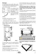
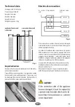
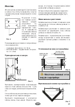
Installation
The emitters should be arranged so that the
user is heated from as many directions as pos-
sible in order to ensure a possibly even heat
treatment.
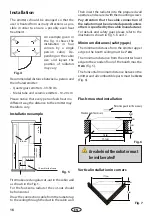
An example given in
the Fig. 4 shows the
installation in four
corners by a single
person cabin. De-
pending on the cabin
size and layout the
position of radiators
may vary.
Fig. 4
Recommended distance between a person and
the infrared emitter:
• Quartz glass emitters - 30-50 cm
• Metal tube and ceramic emitters - 10-20 cm
Please notice that every person feels heat in a
different way, the distance to the emitter may
therefore vary.
min. 50 cm
min. 7 cm
IR-Emitter
Vitae
min. 15 cm
min. 9 cm
at least 9 cm with
additional upper sea
t
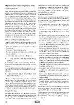
Fig. 5
Installation example
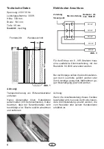
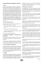
First make a rectangular cut-out in the cabin wall
as shown in the Fig. 1.
For the foot-zone radiator the cut-out should
be horizontal.
Draw the connection cable from the radiator up
to the ceiling through the duct in the cabin wall.
Then insert the radiator into the prepared wall
aperture and secure it with the mounting screws.
Pay attention that the cable connection of
the radiator must be oriented upwards unless
others is specified by the cabin manufacturer.
For details and safety gaps please refer to the
illustrations shown in Fig. 5, 6 and 7.
Minimum distances (safety gaps)
The minimum distance from the emitter upper
edge to the booth ceiling must be
7 cm
.
The minimum distance from the emitter lower
edge to the wooden floor of the booth must be
9 cm
(Fig. 5).
The horizontal minimum distance between the
emitter and all combustible parts must be
4 cm
(Fig. 6).
IR-emitter foot zone
Flush-mounted installation
Fig. 6
Vertical installation in corners
Fig. 7
16 cm
17,1 cm
1,5 cm
5 cm
2 cm
4 cm
1,5 cm
9 cm
17,1 cm
Area behind the radiator must
be well aerated!
Protective guard rail if necessary
Wooden rail if necessary