background image

31

EN

min. 10

105

min. 30 

min. 1900

100 

min. 300 

720 (660/600)

min. 1600

1000

315 

45 

min. 10

min. 30 

min. 40

770 (710/650)

660

80

740

The minimal inner height of the sauna cabin 
shall be 

190 cm

.

The horizontal gap between the sauna heater 
and the cabin wall must be at least 

4 cm

.

The distance between partition wall or sauna 
bench or other flammable materials and the 
sauna heater shall be as shown below on Fig. 1.
The supplied safety grill shall be mounted along 
the top edge of the partition wall between this 
partition wall and sauna wall (Fig. 1). This shall 
prevent that an object may be accidentally 
dropped on the sauna heater.

The distance between the sauna heater and the 
safety grill must be 100 cm as indicated.

!

 Contradictory to the advice con-

cerning the mounting of the sensor of your 
sauna control unit, the temperature sensor 
shall not be mounted on the ceiling above 
the sauna heater but on the side wall as 
shown in the diagram (Fig. 1).

Risk of fire by incorrect sensor installation!

Minimal clearances

Dimensions in mm

1240

1160

Installation example with safety gaps

Height values given in parentheses indicate the possible 
height after the feet adjustment.

Fig. 1

A

A

C

B

D

E

F

A.  Safety grill
B.  Partition wall
C.  Sensor / limiter fuse

D.  Water splash funnel
E.  Sauna heater
F.  Air inlet

Summary of Contents for Invisio Midi

Page 1: ...INNOVATIVE SAUNA TECHNOLOGY MADE IN GERMANY Druck Nr 29344614 35 19 Invisio Midi D Montage und Gebrauchsanweisung Assembly and operating instruction EN RU...

Page 2: ...2 Deutsch 3 English 20 37...

Page 3: ...an 400V 3N AC und Technische Daten 9 Anschluss an 230V 1N AC und Technische Daten 10 Montage Mindestabst nde 11 Montage Basismontage 12 13 Montage des Aufgusstrichters 13 Montage Abschluss 14 Inbetrie...

Page 4: ...die Abluft ffnung in der Kabine nach au en gedr ckt Hierdurch entsteht das typische Saunaklima bei dem in Ihrer Sauna direkt unter der Decke Temperaturen von ca 110 C erreicht werden die durch das Te...

Page 5: ...dgefahr Inspizieren Sie die Saunakabine vor jeder Inbetriebnahme Achten Sie insbe sondere darauf das keine Gegenst nde Wichtige Hinweise Bei unsachgem er Montage be steht Brandgefahr Lesen Sie bitte d...

Page 6: ...eiter verbundenes Metallrohr ge sch tzt werden Den Mindestquerschnitt der Anschlussleitung und die geeignete Kabinengr eimVerh ltniszurAnschluss leistung in kW entnehmen Sie derTabelle Bei der Montage...

Page 7: ...kabel Zuleitung zum Netz und zur Kabinenbeleuchtung vor Besch digung ge sch tzt werden z B durch Verlegung in Installa tionsrohren oder Anbringung von Holzabdeck leisten Das Saunaheizger t darf bei Ze...

Page 8: ...verwenden mit Steuerger ten Econ D2 D4 Emotec D EmoStyle D EmoTouch 3 LSG Leistungsschaltger t Alle Angaben zu Leitungsquerschnitten sind Mindestquerschnitte in mm Kupferleitung Das Saunaheizger t is...

Page 9: ...re Verdrahtung 12 kW U V W N PE U V W N PE 1500 W 1500 W 1500 W 1500 W 1500 W 1500 W 1500 W 1500 W 6 kW U V W N PE N N 9 kW U V W N PE N N 1500 W 1500 W 1500 W 1500 W 1500 W 1500 W 1500 W 1500 W 1500...

Page 10: ...ten f r den Anschluss an 400V 3N AC Anschluss 400 V 3 N 50 Hz AC Nennleistung nach DIN 6 kW 9 kW 12 kW Absicherung Steuerger t 3 x 16 A Absicherung Leistungsschaltger t LSG 3 x 16 A Anschluss Netz Ste...

Page 11: ...NG Das Steuerger t und das Saunaheizger t m ssen f r den Anschluss an 230V 1N AC geeignet sein Verwenden Sie die geeigneten Sicherungen und Kabelleitun gen Brandgefahr und Ger teschaden bei unsachgem...

Page 12: ...en an der Oberkante der Trennwand zur Sauna R ckwand zu montieren Abb 1 Damit soll verhindert werden dass unbeabsichtigt Gegenst nde auf den Ofen fallen Der Abstand von Saunaheizger t bis zur Ober kan...

Page 13: ...offenen Seite nach oben in die seitlich am Ofen angebrauchten F hrungen einschieben Die F e mit je einer Schraube 4 2x9 5 in der gew nschten H he fixieren Anschlie end die beiden Schrauben der Anschl...

Page 14: ...befestigen Sie diese mit jeweils 2 Schrauben 4 2x9 5 proSeiteanderAbdeckung Luftleithaube Das Gef lle der Aufgussrinne muss von dem Aufgussanschluss wegf hren 6 Montage Aufgusstrichter Stecken Sie da...

Page 15: ...erlage Anschlie end den Anschlusskasten wieder mit der Abdeckung und den 4 Schrauben ver schlie en 9 TrennwandundSchutzgittermontieren Montieren Sie dieTrennwand so dass die vorge gebenenMindestabst n...

Page 16: ...n 5 AbdeckungdesAnschlusskastens entfernen 4 Schrauben l sen 6 Steine entfernen 7 Die 2 Befestigungsschrauben des Aufla geblechesf rdieHeizst bel senunddieses nach au en schieben 8 Elektrische Steckve...

Page 17: ...dampf gleichm ig in der Kabine ver teilt und f hrt somit zu einem angenehmen Aufgussempfinden DenkenSiedaran dasssichdieSaunasteinenach jedemAufgusserstwiederneuerhitzenm ssen um einen intensiven Damp...

Page 18: ...htung Brandgefahr Wartung und Pflege Dieses Saunaheizger t ist aus korrosionsarmen Materialen gefertigt Damit Sie lange Freude mit Ihrem Saunaheizger t haben sollten Sie das Ger t warten und pflegen D...

Page 19: ...I Schalter ab gesichert werden Nach dem heutigen Stand der Technik ist es nicht sinnvoll dampfdichte Rohrheizk rper f r Sauna fen einzusetzen Es kann vorkommen dass die Magnesiumoxidf llung der Heizk...

Page 20: ...ycling Bitte diese Adresse zusammen mit der Montageanwei sung gut aufbewahren Damit wir Ihre Fragen schnell und kompetent beantwor ten k nnen geben Sie uns immer die auf dem Typen schild vermerkten Da...

Page 21: ...kte sind f r den St ckgut versand Palette konzipiert Wir weisen an dieser Stelle ausdr cklich darauf hin dass unsereVerpackungen nicht f r den Einzelversand per Paketdienst geeignet sind F r Sch den d...

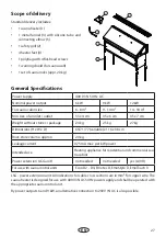
Page 22: ...e of delivery 7 Specifications 8 Installation Minimal clearances 9 Installation 9 Installation basic steps 10 11 Installation of the infusion funnel 11 Installation final steps 12 Commissioning first...

Page 23: ...r compati bility with one another Please note all data and information provided by your sauna supplier The sauna heating units warm your sauna cab in through means of heated air convection To this end...

Page 24: ...e g spruce Only a sauna heater with the appropriate power output may be installed in the sau na cabin Please provide air intake and vent open ings in each sauna cabin The air intakes must always be p...

Page 25: ...a ceiling is maintained Please see also the dimensions diagram for the clearance between the lower edge of the sauna heater and the floor On heaters with bases this clearance is maintained via the bas...

Page 26: ...through the hole to the control unit The cable and all other connecting cables mains power cables and cabin lighting should be installed in installation ducts or also be protected against damage on th...

Page 27: ...SG unit not needed not needed yes L09R For use with sauna control units Econ D2 D4 Emotec D EmoStyle D EmoTouch 3 LSG power extension unit All indications for cable cross sections are in mm for copper...

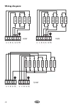
Page 28: ...iring diagram 12 kW U V W N PE U V W N PE 1500 W 1500 W 1500 W 1500 W 1500 W 1500 W 1500 W 1500 W 6 kW U V W N PE N N 9 kW U V W N PE N N 1500 W 1500 W 1500 W 1500 W 1500 W 1500 W 1500 W 1500 W 1500 W...

Page 29: ...12 kW 400V 3N AC 50Hz 400V 3N AC 50Hz Attention Make sure to always connect the N wire Specifications for connection to 400V 1N AC Power supply voltage 400 V 3 N 50 Hz AC Nominal power output 6 kW 9 k...

Page 30: ...o230V 1NAC Makesuretousetheappropriatefuseprotectionandcables Riskofdamagestothe equipment and risk of fire by incorrect installation and connection only for the power range 6 0 9 0 kW Power supply vo...

Page 31: ...all Fig 1 This shall prevent that an object may be accidentally dropped on the sauna heater The distance between the sauna heater and the safety grill must be 100 cm as indicated Contradictory to the...

Page 32: ...ropriate openings in the side corners of the heater housing Fixate each foot with a 4 2x9 5 screw at the re quiredheight Afterthisinsertbackthescrewsof the terminal box panel and secure them 3 Fill th...

Page 33: ...tition wall with 2 screws Payattentionthatthefunnelshouldbeplaced well above the gutter level The mounting place of the funnel should exclude the risk of its accidental touching because it may be very...

Page 34: ...ening in the bot tom of the terminal box and close the terminal box compartment 9 Partition wall and safety grill Installthepartitionwall screen sothatthesafe ty gaps as given on Fig 1 page 8 are obse...

Page 35: ...cover 1 4 screws 4 Remove the cover of the terminal box 6 4 screws 5 Lift up and remove the gutter Take out the rock store 2 6 Remove the sauna rocks 7 Pull out the support frame for heating elments 3...

Page 36: ...steam will quickly rise with the hot up rising air flow and will spread around the sauna cabin from top down delivering the famous loylu steam shock effect Attention Do not pour too much water at onc...

Page 37: ...By daily commercial use we recommend to check the condition of sauna stones every 2 3 months and to reshuffle them By home use the sauna stones need to be checked and reshuffled at least once per year...

Page 38: ...other electrical units will be protected by this ELCB Under current manufacturing technology it is not reasonable to use heating elements for sau na heaters which do not collect moisture from the sur...

Page 39: ...your questions quickly and compe tently please provide the information printed on the type shield including the model item no and serial no in all inquiries Equipment commissioning date ______________...

Page 40: ...roducts is designed for the ship ping of individually packed goods pallet We expressly point out that our packaging is not suitable for individual shipments via parcel post The manufacturer shall acce...

Page 41: ...41 RU 38 38 39 40 41 42 T 43 43 43 44 47 48 49 48 50 50 ASB 51...

Page 42: ...42 RU DIN en ISO 9001 2000 110 30 40 110 20 25 85 80 90...

Page 43: ...43 RU 5 10 1 l 140 40 8 2...

Page 44: ...44 RU 170 C B 76 C...

Page 45: ...00 50 6 9 12 6 8 9 14 14 18 35 x 4 cm 35 x 6 cm 35 x 7 cm 24 kg 25 kg 27 kg x x 65 71 77 x 116 x 38 cm 20 0 75 mA 1 LSG L09R Econ D2 D4 Emotec D EmoStyle D EmoTouch 3 LSG 400 50 6 9 230 50 1 1 1 3 5 1...

Page 46: ...6 RU N 12 kW U V W N PE U V W N PE 1500 W 1500 W 1500 W 1500 W 1500 W 1500 W 1500 W 1500 W 6 kW U V W N PE N N 9 kW U V W N PE N N 1500 W 1500 W 1500 W 1500 W 1500 W 1500 W 1500 W 1500 W 1500 W 1500 W...

Page 47: ...haltger t Power extension unit Extension de puissance Netz Mains R seau 4 Saunasteuerger t Control unit Bo tier de commande Saunaheizger t Sauna heater Po le de sauna 5 5 Netz Mains R seau 12 400V 3N...

Page 48: ...naheizger t saunaheater po ledesauna max 9 0kW U V W N N PE Gr N X Y Z 6 2 5 1 5 6 6 6 2 5 230V 1N 3 x 16A 4 5 6 0 4 7 5 9 0 6 94 2689 230V 1N AC 6 0 9 0 230V 1N 50 Hz AC 6 kW 9 kW 3 x 16 A 3 x 16 A 3...

Page 49: ...49 RU 1 min 10 105 min 30 min 1900 100 min 300 720 660 600 min 1600 1000 315 45 min 10 min 30 min 40 770 710 650 660 80 740 190 c 4 1 1 100 1 1 1240 1160 A A C B D E F A B C D E F...

Page 50: ...50 RU Fig 3 2 4 1 3 2a 3 9 15 2b 2b 1 2a 4 2x9 5 3 4 150 90 30 600 660 720...

Page 51: ...51 RU 6 5 5 6 90 4 4 2 x 9 5 5 90 4...

Page 52: ...52 RU 9 1 5x16 1 8 7 7 10 1 8 4 4 2x9 5 10 4 2 9x9 5...

Page 53: ...53 RU 11 12 13 9 1 2 3 1 5 4 6 4 5 2 6 7 2 3 8 5 9 5 10 11 12 13 3 14 2 15 16 17 18 6 4 19 1 4 20 21...

Page 54: ...54 RU 1 2 4 6 5 3 9 1 2 3 4 5 6 8 10...

Page 55: ...55 RU 100 10 2 3...

Page 56: ...56 RU EOS Saunatechnik GmbH Schneiderstriesch 1 35759 Driedorf Germany EOC 108811 928 7 495 66 55 192 8 800 1000 539 info eos sauna ru www eos sauna ru...

Page 57: ...57 RU ASB I II III IV V VI 24 06 2015...

Reviews: