enware aquablend 2000 Installation Instruction Download Page 1

Installation Instructions

FOR USE IN AUSTRALIA

Call 1300 369 273

www.enware.com.au

Enware Australia Pty Limited 
9 Endeavour Rd Caringbah NSW 2229 Australia 
Ph: +61 2 8556 4000   Fax: +61 2 8556 4055
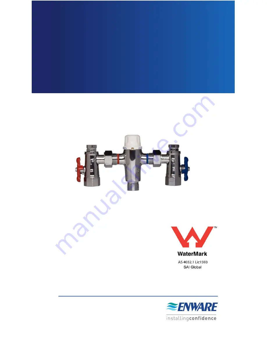
AQUABLEND 2000
THERMOSTATIC
MIXING VALVE

I00109_Jul 16

IS226

Summary of Contents for aquablend 2000

Page 1: ...FOR USE IN AUSTRALIA Call 1300 369 273 www enware com au Enware Australia Pty Limited 9 Endeavour Rd Caringbah NSW 2229 Australia Ph 61 2 8556 4000 Fax 61 2 8556 4055 AQUABLEND 2000 THERMOSTATIC MIXIN...

Page 2: ...the Preparation of this publication which has been issued for guidance only No liability can be accepted for any consequences which may arise as a result of its application Enware trade mark of Enwar...

Page 3: ...tained as per the recommendations outlined in this manual It should be noted however that this valve should not be considered as an alternative to adequate supervision and duty of care during its use...

Page 4: ...orporate union type fittings enabling the thermostatic mixing valve to be removed from its installation without disturbing its pipework The schematics and dimensions of the Aquablend 2000 Male Female...

Page 5: ...r contract to match the water temperature it is exposed to causing the Piston to move thereby regulating the amounts of hot and cold water entering the valve This thermostatic mechanism maintains the...

Page 6: ...gain contract reducing the cold port piston gap and hence supply more hot water and less cold Once again the valve attempts to restore itself to its original setting This will occur for all changing c...

Page 7: ...optimum performance Maximum 38 litres min 300kPA Pressure loss as per flow sizing graph DYNAMIC INLET PRESSURES Hot Cold Inlet Pressures Minimum 20kPa Maximum 500kPa STATIC INLET PRESSURES Hot Cold I...

Page 8: ...k between the valve and the system must be sized in accordance with AS3500 1 to ensure the water velocity in the pipework is within the allowed limit If the valve is to be installed and operated under...

Page 9: ...ction correctly and may put the user in danger It may also void the warranty of the valve Prior to the installation of the valve the system must be checked to ensure that the system operating conditio...

Page 10: ...ectly before the valve inlets To ensure that the mixing valve operates correctly it is necessary that the pipework is thoroughly flushed with clean water before the valve is installed This will remove...

Page 11: ...ervicing heat must not be applied near the mixing valve or inlet fittings as this will damage the valve and inlet fitting internals Failure to comply with this requirement will damage the valve and fi...

Page 12: ...here are no leaks Open the outlet that is serviced by the shortest length of pipe work between the mixing valve and outlet fixture Allow the mixed outlet to flow for at least 60 seconds to allow the t...

Page 13: ...the top cover firmly on to the top of the valve until it snaps back into place 5 Check that the outlet temperature is stable over the full range of flow rates and that the flow rate is adequate for t...

Page 14: ...er supply to the valve After the mixed water temperature has stabilised note the outlet temperature ensuring the outlet temperature has re established Repeat the above test except this time quickly is...

Page 15: ...appropriate action taken if required Ensure a clean dry work area is available A Cleaning the Strainers Isolate the hot and cold supplies to the mixing valve by closing the inlet ball valves Remove th...

Page 16: ...inlet side ensuring it is tighly secured Turn back ON the isolation tap on the HOT inlet Check Non Return Valves on the COLD inlet side repeating steps above using the COLD inlet side C Discharge temp...

Page 17: ...rature differential is not 10 C or greater The piston O ring is damaged Valve body seat Hot Seat is damaged or fouled by debris Cold seat bottom surface of Top Cap is damaged Thermostatic element has...

Page 18: ...nominally balanced to within 10 Mixed water temperature too hot or cold Valve has been tampered with Valve incorrectly set Inlet temperatures are not within specified limits Readjust valve to require...

Page 19: ...t Cap to suit ATMS238 Each ATMS244 Pressure Test Point Plug With O Ring Pair ATMS238 Element and Piston Assembly O Ring Kit ATMS123 Lock Shield Top Cap Assembly OLD STYLE Pressure Test Point Plug With...

Page 20: ...Water Pressure kPa Temp C Temp C Cold Water Supply via Pressure Reducing Valve Fitted YES NO Make of Mixing Valve Model No Size Valve Location Building Valve ID No Total No of Mixing Valves on Site Bu...

Page 21: ...missioned by Signature Licensed Plumber Lic Cert No Business name of Plumbing Contractor Contractors Authority No Date NOTE A duplicate copy of this report is to be retained at the site for any inspec...

Page 22: ...utlets in use 1 outlet in use All req outlets in use 1 2 3 4 5 6 7 8 Give details of brand and model designation Commensurate with the design flow rate for the mixing valve NOTE An accurate digital ty...

Page 23: ...ils Valve installed to requirements of The drawing specification The code of TMV s The code of TMV s The local water supply authority YES NO YES NO YES NO YES NO If NO give details and action taken An...

Page 24: ...rs Authority No Date NOTE A duplicate copy of this report is to be retained at the site for any inspection by authorised persons The following information is to be provided by site manager owner Valve...

Page 25: ...the smaller pressure loss gives the pressure loss ratio For example with a cold supply pressure of 500 kPa a hot supply pressure of 250 kPa and a back pressure of 200 kPa under flow conditions the pr...

Page 26: ...and Territory in Australia Warranty Conditions The valve must have been installed by a licensed plumber in accordance with the ENWARE Installation Instructions and Application Guidelines supplied with...

Page 27: ...hole to faulty manufacture installation of the hot water system of which the valve forms part The valve has failed directly or indirectly as a result of excessive water pressure or temperature outside...

Page 28: ......

Reviews: