Envision EN7400e User Manual Download Page 7

EN7400e

7

12OCT04

EN7400e

Before You Operate the Monitor

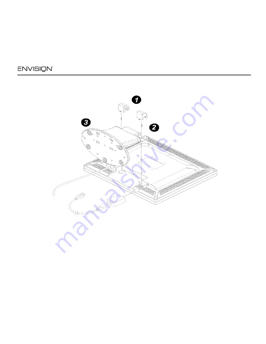
Preparing to Install An Optional Wall Mounting Arm (Not supplied)

This monitor can be attached to a wall mounting 
arm you purchase separately. Disconnect power 
before this procedure. Follow these steps:

1. Pull the screw covers off the back of the 

monitor.

2. Support the base and remove the screws.

3. Remove the base.

See next page for further installation instructions.

Summary of Contents for EN7400e

Page 1: ...EN7400e 1 12OCT04 EN7400e EN7400e 17 inch TFT LCD Monitor User s Manual by Envision Peripherals Inc www ENVISIONdisplay com Before operating your monitor please read this manual thoroughly...

Page 2: ...eceiving antenna 2 Increase the separation between the equipment and receiver 3 Connect the equipment into an outlet on a circuit different from that to which the receiver is connected 4 Consult the d...

Page 3: ...aler or local power company Do not overload power strips and extension cords Overloading can result in fire or electric shock The monitor is equipped with a three pronged grounded plug a plug with a t...

Page 4: ...not lighting up Never attempt to replace it by yourself General Notes Do not install the monitor near heat sources such as radiators or air ducts Do not place monitor in direct sunlight or in areas wi...

Page 5: ...olutions up to 1280 X 1024 pixels 75Hz 1280 x 1024 60Hz Recommended EPA ENERGY STAR Ergonomic Design Space Saving Compact Case Design Package Contents The box that your monitor was shipped in should h...

Page 6: ...power adapter into the DC IN socket on the back of the monitor 4 Plug the other end of the power cord into a grounded AC outlet or UL approved power strip Caution Make sure the power cord is the corre...

Page 7: ...ot supplied This monitor can be attached to a wall mounting arm you purchase separately Disconnect power before this procedure Follow these steps 1 Pull the screw covers off the back of the monitor 2...

Page 8: ...up the holes of the arm with the holes in the back of the monitor 2 Insert the 4 screws into the holes and tighten 3 Insert the power cable into the slot on the back of the monitor The Envisionl EN740...

Page 9: ...e monitor s angle from 5 to 25 Do not touch the LCD screen when you change the angle It may cause damage or breakage Be careful to avoid pinching your hand in the swivel base How to Install INF ICM Fi...

Page 10: ...s If the OSD window is open this button allows you to move within the window and select desired functions Power Press this button to turn the monitor on or off The power indicator will light up Contra...

Page 11: ...o open the function s window 4 Press the or buttons to change the settings of the function 5 To save and exit highlight the EXIT icon and press MENU or leave the monitor alone for 10 seconds If you wa...

Page 12: ...ts identity and depending on the level of DDC used communicate additional information about its display capabilities The communication channel is defined in two levels DDC1 and DDC2B The DDC1 is a uni...

Page 13: ...is ON but there is no video or picture Press a key on the keyboard or wiggle the mouse to re activate the monitor Make sure the video cable is properly connected to the computer Inspect the video cabl...

Page 14: ...or s settings Picture has color defects white does not look white Adjust the settings for Red Green and or Blue colors or select a different color temperature 65 6500 K or 78 7800 K Poor brightness or...

Page 15: ...er s resolution is out of VESA specifications Right click on the desktop and choose Properties Click the Settings tab then set your computer s display mode to one of the settings listed in the resolut...

Page 16: ...0 kHz 83 kHz V Frequency 55 75 Hz Display Colors 16 million colors Dot Clock 135 MHz Maximum Resolution 1280 x 1024 pixels Plug Play VESA DDC1 2BTM Input Connector D Sub 15 pin Input Video Signal Anal...

Page 17: ...ontrast Power Switch MENU Exit External Controls Functions Contrast Brightness Focus Clock H Position V Position Language Dos mode Resolution Selected 6500 K 7800 K RGB Color temp Recall Exit EPA ENER...

Page 18: ...70 Hz 720 x 400 31 47 kHz 70 Hz VGA 640 x 480 31 47 kHz 60 Hz 640 480 35 00 kHz 66 6 Hz 640 480 37 50 kHz 75 Hz SVGA 800 600 37 879 kHz 60 Hz 800 600 46 875 kHz 75 Hz 832 624 49 725 kHz 75 Hz XGA 102...

Page 19: ...dix Connector Pin Assignment Pin Number Description Pin Number Description 1 Red 9 5V 2 Green 10 Detect Cable 3 Blue 11 NC 4 Ground 12 DDC Serial Data 5 Ground 13 H Sync 6 R Ground 14 V Sync 7 G Groun...

Reviews: