


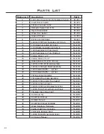


SAMPLE
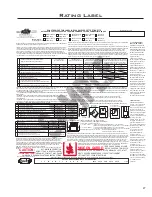
Rating Label
27
U.S. ENVIRONMENTAL
PROTECTION AGENCY
Certified to comply with
2015 particulate emission
standards. Not approved
for sale after May 15, 2020.
This wood heater needs
periodic inspection and
repair for proper
operation. Consult the
owner`s manual for further
information. It is against
federal regulations to
operate this heater in a
manner inconsistent with
the operating instructions
in the owner`s manual.
This heater meets the 2015
U.S. Environmental
Protection Agency’s wood
emission limits for wood
units sold after May 15,
2015. Under specific test
conditions the 1200 heater
has been shown to have a
particulate emission level
of 3.4 g/hr. Under specific
test conditions the 1700
heater has been shown to
have a particulate
emission level of 4.5 g/hr.
ENVIRONMENTAL
PROTECTION AGENCY US
conforme aux normes 2015
d'émission de particules.
Non approuvé pour la vente
après le 15 mai 2020. Ce
poêle à bois doit inspection
et de réparation périodiques
pour un fonctionnement
correct. Consultez le manuel
d'owner`s pour plus
d'informations. Il est contre
les règlements fédéraux
pour faire fonctionner cet
appareil de chauffage d'une
manière incompatible avec
les instructions de
fonctionnement dans le
manuel d'owner`s. Cet
appareil de chauffage
répond aux limites
d'émission de bois de la US
Environmental Protection
Agency 2015 pour les unités
de bois vendus après le 15
mai 2015. Dans des
conditions d'essai
spécifiques du chauffe 1200
a été montré pour avoir un
niveau d'émission de
particules de 3,4 g / h. Dans
des conditions de test
spécifiques au dispositif de
chauffage 1700 a été montré
pour avoir un niveau de 4,5
g / h d'émission de
particules.
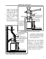
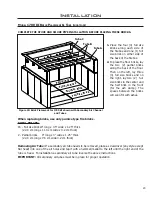
**Alcove (Use double wall pipe) / Alcôve (Utilisant le double connecteur de mur)
I
Total width / Largeur totale
55” (1397 mm)
Model/Modèle 1200
J
Total height / Hauteur totale
78” (1981 mm)
K
Top of stove to ceiling / Le sommet de poêle au plafond
49” (1245 mm)
L
Sidewall to unit / De la paroi latérale au dispositif
Sidewall to connector / De la paroi latérale au connecteur
Backwall to unit / De la paroi arrière au dispositif
Backwall to connector / De la paroi arrière au connecteur
15” (381 mm)
M
24” (610 mm)
N
12” (305 mm)
O
15” (381 mm)
51” (1295 mm)
Model/Modèle 1700
72” (1829 mm)
44” (1118 mm)
13” (330 mm)
22” (559 mm)
8” (203 mm)
11” (279 mm)
Maximum Depth / Profondeur maximum
P
48” (1220 mm)
48” (1220 mm)
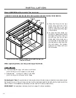
Single wall pipe /
Seul connecteur de mur
**Double wall pipe /
Double connecteur de mur
Top vent out back wall with min. 24” (610mm)
vertical rise; double wall pipe / Donné vent hors
de la paroi arrière avec le min. 24” (610 mm)
l'ascension verticale; double connecteur de mur
A
13” (330 mm)
14” (356 mm)
B
11” (279 mm)
8” (203 mm)
12” (305 mm)
C
9” (229 mm)
6½" (165 mm)
D
22” (559 mm)
22” (559 mm)
23” (584 mm)
E
14” (356 mm)
11” (279 mm)
15” (381 mm)
11” (279 mm)
16” (381 mm)
15” (406 mm)
F
17½” (445 mm)
16½” (419 mm)
10” (254 mm)
8½" (216 mm)
22” (559 mm)
17” (432 mm)
15” (381 mm)
7” (178 mm)
6” (152 mm)
22” (559 mm)
10” (254 mm)
14½” (368 mm)
G
† Front of door opening to edge of hearth /
Le devant d'ouverture de porte au bord de coussin de coeur
USA 16” (406 mm) CND 18” (450 mm)
USA 6” (152 mm) CND 8” (200 mm)
H
Sidewall to unit / De la paroi latérale au dispositif
Sidewall to connector / De la paroi latérale au connecteur
Backwall to unit / De la paroi arrière au dispositif
Backwall to connector / De la paroi arrière au connecteur
Adjacent wall to corner of unit /
De la paroi adjacent au coin de dispositif
Adjacent wall to connector/
De la paroi adjacent au connecteur
1200
20” (508 mm)
12” (305 mm)
10" (254 mm)
29” (737 mm)
15” (381 mm)
18½” (470 mm)
1700
1200
1700
1200
1700
1200
1700
Double wall pipe with efficiency
shield (Flat top model only) / Double
connecteur de mur avec la protection
d'efficacité (Le modèle plat seulement
Model / Modèle
Minimum Clearances to Combustible Materials /
Espaces Libres Aux Materiax Combustibles.
13” (330 mm)
13” (330 mm)
13” (330 mm)
13” (330 mm)
13” (330 mm)
13” (330 mm)
13” (330 mm)
22” (559 mm)
10” (254 mm)
8” (203 mm)
† Side/back of unit to edge of hearth /
Le latérale/arrière de dispositif au bord de coussin de coeur
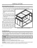
H
H
H
G
B
A
D
E
Front /
Mur avant
Floor Protection /
Protection du sol
K
J
Back wall/
Mur arrière
Sid¸e wall / Mur a côté
N
L
M
O
Alcove Back wall /
Mur d’alcôve a l’arrière
Alcove Side wall / Mur d’alcôve a côté
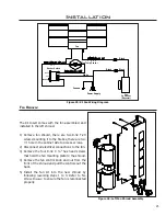
C
F
C
Front /
Mur avant
Adjacent wall /
Mur adjacent
Adjacent wall / Mur adjacent
I
Alcove /
Alcôve
Front /
Mur avant
Front /
Mur avant
Certified for use in Canada & USA /
Certifié pour installation au Canada et aux Etats-Unis.
B
A
D
C
Adjacent
w
al
l / Mur a
dj
acent
F
E
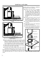
CAUTION: An uninsulated smoke pipe must not pass through an attic, roof space, closet or similar concealed
space, or through a floor, ceiling, wall, or partition, or any combustible construction.
† FLOOR PROTECTION: If a stove is installed on a combustible floor, it must have the legs or pedestal
attached and be on a NON COMBUSTIBLE hearth pad
* ALL CLEARANCES CAN BE REDUCED WITH SHIELDING ACCEPTABLE TO THE LOCAL AUTHORITY.
SINGLE WALL:
IN CANADA: Any ULC-S629 listed chimney system with the accompanying listed single wall vent connector.
IN U.S.A.: Any UL 103 HT listed chimney system with the accompanying listed single wall vent connector.
**DOUBLE WALL :
IN CANADA: Any ULC-S629 listed chimney system with the accompanying listed double wall vent connector.
IN U.S.A.: Any UL 103 HT listed chimney system with the accompanying listed double wall vent connector.
DOUBLEWALL IS REQUIRED FOR MOBILE HOME INSTALLATIONS.
† FLOOR PROTECTION / PROTÉGER LE PLANCHER:
If unit is raised / Si l'appareil est soulevé:
0” - 2” (0mm - 51mm); 1” (25mm) non-combustible material with R = 1.19 or equivalent /
1” (25mm) le matériel incombustible avec la valeur de R = 1.19 ou équivalent.
2” - 8” (51mm - 203mm); ½” (13mm) non-combustible material with R = 1.19 or equivalent /
½” (13mm) le matériel incombustible avec la valeur de R = 1.19 ou équivalent.
Greater than/Plus grand que 8” (203 mm) any non-combustible material /
n'importe quel type de matériel incombustible.
DO NOT REMOVE THIS LABEL / NE PAS ENLEVER CETTE ÉTIQUETTE
LISTED SOLID FUEL SPACE HEATER / IDENTIFIE COMME UN FOYER A COMBUSTIBLE SOLIDE
Models 1200 and 1700 Freestanding units: Room Heater, Solid Fuel Type, Also For Use In Mobile Homes.
Tested to ULC-S627-00, ULC-S628-93 (FPI only), & UL-1482-11.
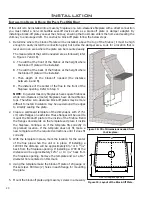
Install and use only in accordance with the manufacturers installation and operating instructions. Contact
local building or fire officials about restrictions and installation inspection in your area. Use 6” (150 mm)
diameter minimum 24 MSG black or 25 MSG blued steel connector listed factory-built chimney suitable for
use with solid fuels or masonry chimney. See local building code and manufacturer’s instructions for
precautions required for passing a chimney through a combustible wall or ceiling. Do not pass chimney
connector through a combustible wall or ceiling. Minimum clearances from horizontal connector and ceiling
18” (455 mm). Do not connect this unit to a chimney flue servicing another appliance.
Modèles 1200 et 1700 items indépendants: Chauffage pièce, le type de combustible solide, également pour une utilisation dans
les maisons mobiles. Testé selon ULC-S627-00, ULC-S628-93 (FPI seulement), & UL-1482-11.
Ce dispositif doit entre installé et opéré conformément aux instructions d'installation et d'opération du manufacturier contactez le
service local de l'inspection des bâtiments ou l'officier pompier concernant les restrictions et l'inspection d'installation dans votre
localité. Utiliser des connecteurs répertoriés 24 MSG noir ou 25 MSG en acier bronzée de 6" (150 mm) minimum, et une
cheminée de fabrication industrielle, appropriée pour utilisation avec des combustibles solides ou avec une cheminée de
maçonnerie. Vérifiez les précautions a prendre exigées parle code local et les instructions du manufacturier concernant les
conditions pour passer la cheminée a travers un mur ou un plafond combustible. Net pas installer le connecteur de la cheminée
a travers un mur ou un plafond combustible. Espaces libres minimum d'un connecteur horizontal et plafond sont 18" (455 mm)
ne pas connecter ce dispositif a un conduit de cheminée qui sert déjà un autre dispositif.
DATE OF MANUFACTURE / DATE DE FABRICATION:
J F M A M J J A S O N D 2015 2016 2017 2018 2019
C-14615
MANUFACTURED BY / FABRIQUE PAR: SHERWOOD INDUSTRIES LTD. 6782 OLDFIELD ROAD, SAANICHTON, BC CANADA
MADE IN CANADA / FABRIQUE AU CANADA
HOT WHILE IN OPERATION.
DO NOT TOUCH. KEEP CHILDREN,
CLOTHING AND FURNITURE AWAY. CONTACT MAY CAUSE
SKIN BURN. READ NAMEPLATE AND INSTRUCTIONS.
CAUTION:
TRÈS CHAUD QUAND ALLUMÉ.
NE TOUCHEZ PAS. TENIR LOIS
LES ENFANTS, LES VÊTEMENTS ET LES MEUBLES. LE CONTACT
PEUT CAUSER DES BRÛLURES. LISEZ ATTENTIVEMENT
L’ÉTIQUETTE ET LES INSTRUCTIONS.
MISE EN GARDE:
OPERATE ONLY WITH DOORS CLOSED. Only open door to feed fire. For use with solid wood
fuels only. Do not use any other type of fuel. Do not use grate or elevate-fire build wood fire directly
on hearth. Do not overfire. Do not obstruct beneath the heater. If heater or chimney connector
glows, you are overfiring. Inspect and clean chimney frequently-under certain conditions of use,
creosote buildup may occur rapidly. The provided insulation materials are required for operation.
Keep furnishing and other combustibles well away from heater. Replace glass only with 5 mm thick
ceramic glass. Optional component for FS: fan, electrical rating 115V, 60 Hz 1 Amp (Part #
EFW-261). Combustion air openings are not to be obstructed.
Danger:
Risk of electrical shock. Disconnect power before servicing unit. Route cord away from
heater.
Models 1200 and 1700 inserts may be installed as an insert in a masonry fireplace. / On peut encastrer le modèles 1200 et 1700 dans un foyer de maçonnerie.
L’OPERATION DU POELE DOIT SE FAIRE AVEC LA PORTE FERME. N'ouvrir la porte que pour alimenter le feu. N'utilisez que
des combustibles solides. Ne pas utiliser un autre type de carburant. N'employez pas de grille de foyer ou ne surélevez pas le feu.
Mettez le bois à brûler directement sur l'âtre. Pour éviter la surchauffeur, ne mettez pas trop de bois. N'obstruez pas les ouvertures
d'air comburant. Si le poêle ou le connecteur commencent à luire, vous surchauffez le poêle. Inspectez et nettoyez la cheminée
souvent. Dans certaines conditions, le créosoté peut s'accumuler rapidement. Les matériaux d'isolation fournis sont requis pour
l'opération.Tenez loin les meubles et d'autres produits combustibles. Ne remplacez le verre qu'avec du verre céramique, 5mm
MISE EN GARDE: Un uninsulated tuyau de fumée ne doit pas passer par un grenier, un espace de toit, le placard ou
l'espace dissimulé similaire, ou par un plancher, un plafond, un mur, ou une cloison, ou une construction combustible.
† PROTÉGER LE PLANCHER: Si une cuisinière est installée sur un sol combustible, il doit avoir un piédestal attache et
être sur un coussinet non- combustible.
TOUS “ESPACES LIBRES AUX MATERIAX COMBUSTIBLES” PEUVENT ÊTRE RÉDUITS AVEC PROTÉGEANT
ACCEPTABLE À L’AUTORITÉ LOCALE.
Seul Connecteur de Mur:
Au Canada: Certifiée seul connecteur de mur avec toute systèmes de cheminée listée sous ULC-S629.
Aux États-Unis: Certifiée seul connecteur de mur avec toute systèmes de cheminée listée sous UL 103 HT.
**Double Connecteur de Mur:
Au Canada: Certifiée double connecteur de mur avec toute systèmes de cheminée listée sous ULC-S629.
Aux États-Unis: Certifiée double connecteur de mur avec toute systèmes de cheminée listée sous UL 103 HT.
DOUBLE CONNECTEUR DE MUR NÉCESSAIRES POUR INSTALLATION DANS LES MAISONS
MOBILE.
Tested &
Listed By
Model / Modèle
1200 FPI 1700 FPI
A To unshielded side wall / aux mur non protegé
10” (254 mm) 10” (254 mm)
B To an unshielded 8” (203 mm) mantle / aux manteau 8“ non protegé
21” (533 mm) 24” (610 mm)
C To top facing (protruding ¾” [19 mm]) clearance / aux revêtement supérieur 17½” (445 mm) 19½” (495 mm)
D To side facing (protruding ¾” [19 mm]) clearance / aux revêtement a côté 1” (25 mm) 1” (25 mm)
E † From door opening of unit to edge of floor protection /
De ouverture de la porte de l'unité à bord de la protection de plancher USA 16” (406mm) / CND 18” (450mm)
F † From side of unit to edge of floor protection /
Du côté de l'unité au bord de la protection de plancher USA 6” (152 mm) / CND 8” (200 mm)
épais. Équipement en option pour un FS: ventilateur caractéristiques assignées 115V, 60 Hz, 1 Amp (pièce
# EFW-261) tenez le câble électrique loin du poêle.
Danger:
Le risque de choc électrique. Débrancher le
dispositif avant d'entretenir. Ouvertures d'air de combustion ne doivent pas être obstrués.
Model
/ Modèle:
Report/Rapport no.
Kodiak 1200 FS
268-S-04b-2
Venice 1200 FPI
268-S-05-2
1200 KI FPI
268-S-05-2
Boston 1200 FPI
268-S-06c-2
Kodiak 1700 FS
268-S-01b-2
Venice 1700 FPI
268-S-06c-2
1700 KI FPI
268-S-06c-2
Boston 1700 FPI
268-S-06c-2
Boston 1200 FS
268-S-04b-2
Boston 1700 FS
268-S-01b-2
Serial No. / No. De Serié:
Summary of Contents for Kodiak 1200 FPI
Page 30: ...Notes 30 ...


