background image

Installing XFPs

2-8 Hardware Installation

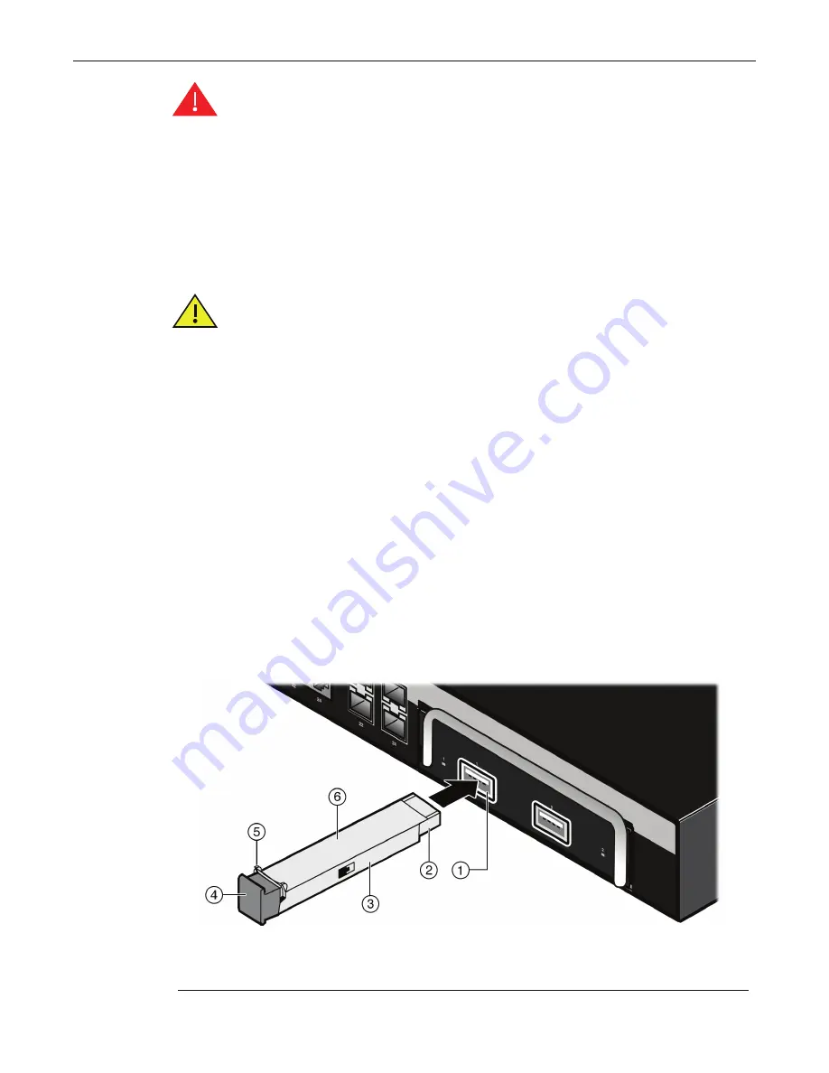
Installing an XFP

To


install


an


XFP,


refer


to


Figure 2

4

,


and


proceed


as


follows:

1.

Hold


the


XFP


with


the


top


side


positioned


as


shown,


and


the


edge


connector


facing


the


port


slot.

2.

Align


the


XFP


with


the


port


slot.

3.

Push


the


XFP


into


the


port


slot


until


the


XFP


“clicks”


and


locks


into


place.

Figure 2-4  XFP with LC Connector

Warning: 

Fiber-optic XFPs use Class 1 lasers. Do not use optical instruments to view the 

laser output. The use of optical instruments to view laser output increases eye hazard. 
When viewing the output optical port, power must be removed from the network adapter.

Advertencia: 

Los XFPs de fibra optica usan lasers de clase 1. No se debe usar 

instrumentos opticos para ver la potencia laser. El uso de los instrumentos opticos para 
ver la potencia laser incrementa el riesgo a los ojos. Cuando vean el puerto de la potencia 
optica, la corriente debe ser removida del adaptador de la red.

Warnhinweis:

 XFPs mit Fiber-Optik Technologie benutzen Laser der Klasse 1. Benutzen 

sie keinesfalls optische Hilfsmittel, um die Funktion des Lasers zu überprüfen. Solche 
Hilfsmittel erhöhen die Gefahr von Sehschäden. Wenn sie den optischen Port überprüfen 
möchten stellen Sie sicher, dass die Komponente von der Spannungsversorgung getrennt 
ist.

Caution: 

Carefully follow the instructions in this manual to avoid damaging the XFP and 

switch.

The XFP and switch are sensitive to static discharges. Use an antistatic wrist strap and 
observe all static precautions during this procedure. Failure to do so could result in 
damage to the XFP and switch. Always leave the XFP in the antistatic bag or an equivalent 
antistatic container when not installed.

Precaución:

 Siga las instrucciones del manual para no dañar el XFP ni del aparato, 

puesto que son muy sensible a las descargas de electricidad estática. Utilice la pulsera 
antiestática y tome todas las precauciones necesarias durante este procedimiento. Si no 
lo hace, podría dañar el XFP o del aparato. Mientras no esté instalado, mantenga el XFP 
en su bolsa antiestática o en cualquier otro recipiente antiestático.

1

Port slot 

4

Protective dust cover

2

Edge connector (insertion side)

5

Wire handle (for XFP release)

3

XFP 

6

XFP,


top side

Summary of Contents for SecureStack C3K-2XFP IOM

Page 1: ...P N 9034396 01 Enterasys SecureStack C3 Gigabit Ethernet Switch Hardware Installation Guide C3K122 24 C3K122 24P C3K172 24 C3K 2XFP ...

Page 2: ......

Page 3: ...rks Inc All rights reserved Part Number 9034396 01 September 2008 ENTERASYS ENTERASYS NETWORKS ENTERASYS SECURE NETWORKS NETSIGHT ENTERASYS NETSIGHT SECURESTACK ENTERASYS SECURESTACK and any logos associated therewith are trademarks or registered trademarks of Enterasys Networks Inc in the United States and or other countries For a complete list of Enterasys trademarks see http www enterasys com c...

Page 4: ...ustry Canada Notice This digital apparatus does not exceed the class A limits for radio noise emissions from digital apparatus set out in the Radio Interference Regulations of the Canadian Department of Communications Le présent appareil numérique n émet pas de bruits radioélectriques dépassant les limites applicables aux appareils numériques de la class A prescrites dans le Règlement sur le broui...

Page 5: ...ical and electronic equipment is required and that this product was placed on the European market after August 13 2005 the date of enforcement for Directive 2002 96 EC 2 When this product has reached the end of its serviceable life it cannot be disposed of as unsorted municipal waste It must be collected and treated separately 3 It has been determined by the European Parliament that there are pote...

Page 6: ...ials in the parts is above the relevant threshold of the SJ T 11363 2006 standard ᇍ䫔ଂП᮹ⱘ᠔ଂѻક ᴀ㸼ᰒ ߃ կᑨ䫒ⱘ ᄤֵᙃѻકৃ㛑ࣙ 䖭ѯ 䋼DŽ ᛣ ᠔ଂѻકЁৃ㛑Ӯгৃ㛑ϡӮ ᠔ ᠔ ⱘ䚼ӊDŽ This table shows where these substances may be found in the supply chain of Enterasys electronic information products as of the date of sale of the enclosed product Note that some of the component types listed above may or may not be a part of the enclosed...

Page 7: ... fiber under normal conditions is 12 6 dBm or 55 x 10 6 watts Removing the optical connector from the transceiver allows laser radiation to emit directly from the optical port The maximum radiance from the optical port under worst case conditions is 0 8 W cm 2 or 8 x 10³ W m2 sr 1 Do not use optical instruments to view the laser output The use of optical instruments to view laser output increases ...

Page 8: ...ury Business Park London Road Newbury Berkshire RG14 2PZ England Conformance to Directive s Product Standards EC Directive 2004 108 EC EN 55022 2006 EN 55024 1998 EN 61000 3 2 2000 EN 61000 3 3 1995 EC Directive 2006 95 EC EN 60950 1 2001 EN 60825 1 1994 EN 60825 2 2004 Equipment Type Environment Information Technology Equipment for use in a Commercial or Light Industrial Environment Enterasys Net...

Page 9: ...perability except to the extent expressly permitted by applicable law and to the extent the parties shall not be permitted by that applicable law such rights are expressly excluded Information necessary to achieve interoperability or correct errors is available from Enterasys upon request and upon payment of Enterasys applicable fee b Incorporate the Program in whole or in part in any other produc...

Page 10: ...s showing i license fees due and paid and ii the use copying and deployment of the Program You also grant to Enterasys and its authorized representatives upon reasonable notice the right to audit and examine during Your normal business hours Your books records accounts and hardware devices upon which the Program may be deployed to verify compliance with this Agreement including the verification of...

Page 11: ...nforced to the maximum extent permissible Any such invalidity illegality or unenforceability in any jurisdiction shall not invalidate or render illegal or unenforceable such provision in any other jurisdiction 14 TERMINATION Enterasys may terminate this Agreement immediately upon Your breach of any of the terms and conditions of this Agreement Upon any such termination You shall immediately cease ...

Page 12: ...xii ...

Page 13: ...llation Prerequisites 2 2 Necessary Tools 2 2 Unpacking the C3K Switch 2 2 Installing the C3K 2XFP Input Output Module 2 3 Unpacking the C3K 2XFP IOM 2 3 Installing the C3K 2XFP into the C3K Switch 2 3 Removing the C3K 2XFP from the C3K Switch 2 4 Installing Mini GBICs 2 5 Preparing a Mini GBIC for Installation 2 5 Installing a Mini GBIC 2 5 Removing a Mini GBIC 2 7 Installing XFPs 2 7 Preparing a...

Page 14: ...ial Switch Management Logon 2 28 Chapter 3 Troubleshooting Using LANVIEW 3 2 Troubleshooting Checklist 3 5 Using the Password Reset Button 3 6 Appendix A Specifications Switch Specifications A 2 C3K122 24 A 2 C3K122 24P A 3 C3K172 24 A 4 C3K 2XFP Specifications A 5 1 Gigabit Ethernet and 100Base FX Transceiver SFP Specifications A 6 MGBIC LC01 MGBIC MT01 Specifications 1000BASE SX A 6 MGBIC 02 Spe...

Page 15: ...e following table Important Notice Depending on the firmware version used in your C3K switch some features described in this document may not be supported Refer to the Release Notes shipped with the switch to determine which features are supported Electrical Hazard Only qualified personnel should perform installation procedures Riesgo Electrico Solamente personal calificado debe realizar procedimi...

Page 16: ...n that may be of special importance Caution Contains information essential to avoid damage to the equipment Precaución Contiene información esencial para prevenir dañar el equipo Achtung Verweißt auf wichtige Informationen zum Schutz gegen Beschädigungen Electrical Hazard Warns against an action that could result in personal injury or death due to an electrical hazard Riesgo Electrico Advierte con...

Page 17: ...pport have the following data ready Your Enterasys Networks service contract number if applicable A description of the failure A description of any action s already taken to resolve the problem for example changing mode switches or rebooting the unit The serial and revision numbers of all involved Enterasys Networks products in the network A description of your network environment such as layout c...

Page 18: ...Getting Help xviii About This Guide The device history for example if you have returned the device before or if this is a recurring problem Any previous Return Material Authorization RMA numbers ...

Page 19: ...nch rack Connectable to a network backbone of up to eight total switches using high speed stack connections Configuration of switch functions using Enterasys WebView application CLI switching commands and or SNMP C3K switches are described in detail in the following sections Important Notice Depending on the firmware version used in the switch some features described in this document may not be su...

Page 20: ...or the optional C3K 2XFP Input Output Module IOM For more information about the C3K 2XFP see C3K 2XFP Input Output Module on page 1 4 Figure 1 1 C3K122 24 and C3K122 24P Shown with Optional C3K 2XFP Caution The C3K122 24 is not a PoE compliant device Do not connect a SecureStack C2 PoE Redundant Power System C2RPS POE to the power connector Otherwise damage to the device may result Precaución El d...

Page 21: ...SYS using a C2RPS PSM Cable Slot for the optional C3K 2XFP Input Output Module IOM Figure 1 2 C3K172 24 Shown with Optional C3K 2XFP Caution The C3K172 24 is not a PoE compliant device Do not connect a SecureStack C2 PoE Redundant Power System C2RPS POE to the power connector Otherwise damage to the device may result Precaución El dispositivo C3K172 24 no cumple con el estándar PoE No conecte una ...

Page 22: ...nnectors for high speed connections in a stack configuration The high speed stacking cables used for the connections are optional items and must be ordered separately See Connecting High Speed Stacking Cables on page 2 13 for more information about high speed stack connections and available cables Redundant Power Supply Capability The switch has redundant power supply capability when connected to ...

Page 23: ...ying 15 4 watts of power to all ports simultaneously Powered Device Classifications PDs are devices that receive their operating 48 Vdc power through a new or existing Ethernet cable from a switch or other device that can provide a PoE compliant port connection This enables the PD to operate in a location without local power For example Devices such as PoE compliant remote EXIT signs and Personal ...

Page 24: ...x operation IEEE 802 3x Flow Control support Full Duplex mode The SFP ports are compliant with the following standards and operations IEEE 802 3z IEEE 802 3x Flow Control support for Full Duplex mode Auto negotiation for Full Duplex control operation The XFP ports are compliant with the following standards and operations IEEE 802 3ae 10GbE The stacking port provides 48 Gbps per port connected to M...

Page 25: ...ectrico Solamente personal calificado debe realizar procedimientos de instalacion Elektrischer Gefahrenhinweis Installationen sollten nur durch ausgebildetes und qualifiziertes Personal vorgenommen werden For information about Refer to page Installation Prerequisites 2 2 Necessary Tools 2 2 Unpacking the C3K Switch 2 2 Installing the C3K 2XFP Input Output Module 2 3 Installing Mini GBICs 2 5 Insta...

Page 26: ...ial protecting the switch 2 Verify the carton contents with the items listed in Table 2 1 3 Remove the tape seal on the non conductive bag to remove the switch 4 Perform a visual inspection of the switch for any signs of physical damage Contact Enterasys Networks if there are any signs of damage See Getting Help on page xvii for more information on contacting Enterasys Networks Table 2 1 Contents ...

Page 27: ... a visual inspection of the C3K 2XFP for any signs of physical damage Contact Enterasys Networks if there are any signs of damage See Getting Help on page xvii for more information on contacting Enterasys Networks Installing the C3K 2XFP into the C3K Switch This section describes how to install the optional C3K 2XFP into your C3K switch The C3K switch must be powered off before installing the C3K ...

Page 28: ... removing the C3K 2XFP IOM To remove the C3K 2XFP IOM from your C3K switch 1 Power off your C3K switch 2 Disconnect cabling and XFPs from the module 3 Loosen the two captive screws on the front of the C3K 2XFP IOM 4 Using the C3K 2XFP s handle gently remove the C3K 2XFP IOM from your C3K switch 5 If storing your C3K 2XFP IOM insert the C3K 2XFP into antistatic packaging 6 Return the coverplate to ...

Page 29: ...the SFP port slot until the Mini GBIC clicks and locks into place Warning Do not use optical instruments to view laser output The use of optical instruments to view laser output increases eye hazard Advertencia No utilizar instrumentos opticos para ver el laser El uso de instrumentos opticos para ver el laser incrementa el riesgo de perdida de la vision Warnhinweis Benutzen sie keinesfalls optisch...

Page 30: ...gure 2 3 Mini GBIC with LC Connector 1 Port slot 4 Protective dust cover 2 Release tab 5 7 pin edge connector insertion side 3 Mini GBIC MGBIC MT01 shown 6 Mini GBIC top side 1 Port slot 4 Protective dust cover 2 Release tab 5 Mini GBIC 3 7 pin edge connector insertion side 6 Mini GBIC top side ...

Page 31: ...oving the XFP from the antistatic packaging it is recommended that you use an antistatic wrist strap not supplied to prevent damage from static discharge To use the wrist strap refer to the instructions provided with your antistatic wrist strap 1 Remove the XFP from its packaging 2 If there is a protective dust cover on the XFP connector do not remove it at this time Caution Do NOT remove a Mini G...

Page 32: ...Klasse 1 Benutzen sie keinesfalls optische Hilfsmittel um die Funktion des Lasers zu überprüfen Solche Hilfsmittel erhöhen die Gefahr von Sehschäden Wenn sie den optischen Port überprüfen möchten stellen Sie sicher dass die Komponente von der Spannungsversorgung getrennt ist Caution Carefully follow the instructions in this manual to avoid damaging the XFP and switch The XFP and switch are sensiti...

Page 33: ...eet is optional if you are installing the switch in a rack To install the rubber feet proceed to Installing the Rubber Feet instructions below For instructions to rack mount the switch proceed to Mounting a C3K Switch in a 19 Inch Rack on page 2 11 Caution Do NOT remove the XFP from the port slot without releasing it The XFP is released by pulling down on its wire handle Attempting to remove the X...

Page 34: ...Surface Locate the switch within 152 cm 5 ft of its power source and on a surface as shown in Figure 2 5 If an optional redundant power system is going to be installed and connected to the 14 pin Redundant Power Supply input connector on the rear of the switch refer to the installation guide shipped with the redundant power system The next step to install the switch is dependent on the type of ins...

Page 35: ...switch in a 19 inch rack you need Two rackmount brackets and mounting screws rackmount kit shipped with the switch Four user supplied screws to attach the switch to a standard 19 inch rack 1 Approximately 152 cm 5 ft from power source 3 44 5 cm 19 4 in for proper ventilation 2 4 45 cm 1 75 in per switch Vertical clearance depends on number of switches stacked 4 419 0 cm 16 5 in for proper ventilat...

Page 36: ...e eight M3 x 6 mm flathead screws shipped with the switch Figure 2 6 Attaching the Rackmount Brackets Note To ensure proper ventilation and prevent overheating leave a minimum clearance space of 5 1 cm 2 0 in at the left right and rear of the switch Warning Before rack mounting the device ensure that the rack can support it without compromising stability Otherwise personal injury and or equipment ...

Page 37: ...ng Cables on page 2 13 Otherwise proceed to Connect AC and RPS Power on page 2 17 Connecting High Speed Stacking Cables The stack of switches can be connected in a ring or daisy chain topology In a ring topology all the switches are connected The only difference in the cable connections in a daisy chain topology is that one cable is not installed Up to 8 switches can be stacked together and connec...

Page 38: ... speed stacking cable connection from the STACK DOWN connector of the switch at the top of the stack to the STACK UP connector at the bottom of the stack completes the ring connection In a daisy chain topology one cable is not used Figure 2 8 High Speed Stacking Cable Connections After connecting the cables to the stacking ports proceed to Configuring Switches in a Stack on page 2 15 for instructi...

Page 39: ... of backup manager is also determined in case the current manager malfunctions is powered down or is disconnected from the stack The console port on the manager switch remains active for out of band local switch management but the console port on each member switch is deactivated This enables you to set the IP address and system password using a single console port Now each switch can be configure...

Page 40: ...signment according to the physical position in a stack When you power up each switch and allow it to become fully operational before applying power to the next switch the first one becomes the Manager and all the next switches will join that stack regardless of Priority Firmware Revision or MAC Address The switches are assigned unit IDs in the order that you power on each switch 2 Optional If desi...

Page 41: ...onnect a switch to the AC power source refer to Figure 2 9 on page 2 18 and proceed as follows 1 Plug the power cord into the switch AC power connector 2 Plug the other end of the power cord into a dedicated grounded AC outlet not shown The type of power outlet and power cord are country dependent Important Considerations About Using Clear Config in a Stack When using the clear config command as d...

Page 42: ...nnecting to Console Port for Local Management on page 2 19 If you are installing the switch in a stack configuration apply power to each switch in order according to the procedure you use in Configuring Switches in a Stack on page 2 15 1 AC power cord 2 AC power connector 3 Connector for external redundant power supply Note If the CPU LED illuminates solid red there was a critical failure For more...

Page 43: ...eded to connect the DB9 male Console port connector on the switch The cables are terminated by a DB9 female connector at one end and by one of three type connectors at the other end depending on the type connection needed for the remote device The compatible cables are as follows DB9 female to DB9 female included DB9 female to DB25 female DB9 female to DB25 male Using a DTE modem DB9 female to DB9...

Page 44: ...lug the DB9 female connector at the other end of cable into the communications port on the PC 3 Turn on the PC and configure your VT emulation package with the following parameters When these parameters are set the Startup screen will display Proceed to Connecting to the Network on page 2 23 Figure 2 11 Connecting an IBM PC or Compatible 1 Pin 2 Received Data input 2 Pin 3 Transmitted Data output ...

Page 45: ...nager connect to its Console port 2 Plug the DB25 female connector at the other end of the cable into the port labeled COMM on the VT terminal 3 Turn on the terminal and access the Setup Directory Set the following parameters on your terminal When these parameters are set the Startup screen will display Proceed to Connecting to the Network on page 2 23 Figure 2 12 Connecting a VT Series Terminal P...

Page 46: ...of the cable into the modem communications port 3 Turn on the modem and make sure the remote modem is ON 4 With your PC connected to the remote modem configure your VT emulation package with the following parameters When these parameters are set the Startup screen will display If the switches are in a stacked configuration proceed to Connecting to the Network on page 2 23 Figure 2 13 Connecting to...

Page 47: ...t the other end of the segment is powered ON 2 Connect the twisted pair segment to the switch by inserting the RJ45 connector on the twisted pair segment into the desired RJ45 port for example Port 8 Figure 2 14 Connecting a UTP Cable Segment to RJ45 port 3 Verify that a link exists by checking that the Link Activity LED is ON solid green or blinking green If the Link Activity LED is OFF perform t...

Page 48: ...ng Guide Refer to Related Documents on page xvi for information on obtaining this document 4 If a link is not established contact Enterasys Networks Refer to Getting Help on page 1 5 for details Repeat all steps above until all connections have been made Figure 2 15 Four Wire Crossover Cable RJ45 Pinouts for 10 100BASE TX Figure 2 16 Four Wire Straight Through Cable RJ45 Pinouts for 10 100BASE TX ...

Page 49: ...Cable RJ45 Pinouts for 10 100 1000BASE TX 1 RJ45 device port 2 Other device port 3 RJ45 to RJ45 crossover cable 1 RJ45 device port 2 Other device port 3 RJ45 to RJ45 straight through cable 2 1 3 6 4 5 7 8 TX1 TX2 RX4 RX1 TX4 RX3 TX3 RX2 TX2 TX1 RX3 RX2 TX3 RX4 TX4 RX1 2 1 3 6 4 5 7 8 Â Á À TX1 TX2 RX4 RX1 TX4 RX3 TX3 RX2 2 1 3 6 4 5 7 8 TX2 TX1 RX3 RX2 TX3 RX4 TX4 RX1 2 1 3 6 4 5 7 8 Â À Á ...

Page 50: ...ncia Los XFPs Mini GBICs de fibra optica usan lasers de clase 1 No se debe usar instrumentos opticos para ver la potencia laser El uso de los instrumentos opticos para ver la potencia laser incrementa el riesgo a los ojos Cuando vean el puerto de la potencia optica la corriente debe ser removida del adaptador de la red Warnhinweis XFPs Mini GBICs mit Fiber Optik Technologie benutzen Laser der Klas...

Page 51: ...eps until it is on a Verify that the device at the other end of the segment is ON and connected to the segment b If there are separate fiber optic connections on the other device check the crossover of the cables Swap the cable connections if necessary c Check that the fiber optic connection meets the dB loss and cable specifications outlined in the Cabling Guide for multimode mode cabling To obta...

Page 52: ...password and perform more involved management configurations on the switch One of many capabilities is to reconfigure the stack reassigning the Manager function to another switch and configuring the order of Member switches that will take over the stack management functions in case the operating Manager is powered down malfunctions or is removed from the stack 4 After the initial configuration you...

Page 53: ...ct customer service for repair For information about Refer to page Using LANVIEW 3 2 Troubleshooting Checklist 3 5 Using the Password Reset Button 3 6 Caution There is a risk of explosion if the battery is replaced with an incorrect type Dispose of used batteries according to instructions supplied with the batteries Precaucion Hay riesgo de explosion si la bateria se reemplaza con el typo incorrec...

Page 54: ...1 on page 3 3 describes the LED indications and provides recommended actions as appropriate 1 CPU LED 5 Manager LED 2 STACK DOWN LED 6 Link Activity LED for RJ45 ports 1 through 24 3 STACK UP LED 7 Link Activity LED for Combo SFP ports 21 through 24 4 RPS LED for redundant power source status 8 Link Activity LEDs for XFP ports 25 and 26 Note The terms flashing blinking and solid used in Table 3 1 ...

Page 55: ...several minutes contact Enterasys Networks for technical support Blinking Code image is being downloaded None Green Solid System is fully functional None Blinking Boot up in process None DOWN Off No valid connection to switch stackup connector 1 Make sure the switch connected to the stackup connector is powered on 2 Replace cable with a known good one 3 If the problem still exists contact Enterasy...

Page 56: ... AC power source 3 Replace the power cord with a known good one 4 Ensure the DC power cord from the RPS to the switch is plugged in correctly 5 If the problem persists contact Enterasys Networks for technical support Amber Solid The switch internal power supply failed and the RPS is providing the proper power to the switch None Link Activity Off 1 No link 2 No activity or port in standby None None...

Page 57: ...3 Configuration Guide for the Community Names Table setup Cannot contact the switch through in band management IP address not assigned Refer to the SecureStack C3 Configuration Guide for the IP address assignment procedure Port is disabled This is normal if the switch is a Member in a stack If operating as a standalone switch or as the Manager in a stack enable the port Refer to the SecureStack C3...

Page 58: ... be indicated via CLI only 2 Logon to device management You can now logon to the switch via the Console port and assign a new password using the command line interface CLI 3 To access switch management from your local PC terminal or modem connection refer to the SecureStack C3 Configuration Guide for instructions on how to log in and enter a new password The guide is available online at http www e...

Page 59: ...es the right to change the specifications at any time without notice For information about Refer to page Switch Specifications A 2 C3K 2XFP Specifications A 5 1 Gigabit Ethernet and 100Base FX Transceiver SFP Specifications A 6 10 Gigabit Ethernet Transceiver XFP Specifications A 10 Console Port Pinout Assignments A 11 Regulatory Compliance A 12 ...

Page 60: ...0BASE FX 1000BASE LX SX fiber optic connections and 1000BASE T copper connections When an SFP transceiver Mini GBIC that is installed in ports 21 through 24 establishes a link the associated fixed front panel RJ45 10BASE T 100BASE TX 1000BASE T port is disabled Physical Dimensions 354 40L x 441 0W x 44 0H mm Approximate Weight 11 3 lbs 5 125 kg Predicted hours for Mean Time Between Failures MTBF 1...

Page 61: ...upport optional Mini GBICs 100BASE FX 1000BASE LX SX fiber optic connections and 1000BASE T copper connections When an SFP transceiver Mini GBIC that is installed in ports 21 through 24 establishes a link the associated fixed front panel RJ45 10BASE T 100BASE TX 1000BASE T port is disabled Physical Dimensions 354 40 x 441 0 x 44 0 mm Approximate Weight 13 9 lbs 6 325 kg Predicted hours for Mean Ti...

Page 62: ...ni GBICs 100BASE FX 1000BASE LX SX fiber optic connections and 1000BASE T copper connections Physical Dimensions 354 40 x 441 0 x 44 0 mm Approximate Weight 11 2 lbs 5 075 kg Predicted hours for Mean Time Between Failures MTBF 166 032 hours Heat Dissipation maximum 65 4 W 223 1 BTUh AC Input Specifications Input Voltage 100 to 240 VAC Input Current 1 5A Frequency 50 to 60 Hz Environmental Operatin...

Page 63: ...A 4 C3K 2XFP IOM Specifications Item Specification XFP ports Two XFP ports that support 10 Gigabit Ethernet connections Physical Dimensions 170 00 x 131 15 x 33 30 mm Approximate Weight 99 lbs 0 45 kg Predicted hours for Mean Time Between Failures MTBF 704 995 Heat Dissipation maximum 17 W Environmental Operating Temperature 0ºC to 50ºC Storage Temperature 40ºC to 70ºC Operating Relative Humidity ...

Page 64: ...r optic multimode port that is compliant with the 1000BASE SX stan dard and has an LC duplex style connector MGBIC LC04 1 LC fiber optic multimode port that is compliant with the 100BASE FX stan dard and has an LC connector MGBIC LC05 1 LC fiber optic single mode port that is compliant with the 100BASE FX standard and has an LC connector MGBIC LC07 1 LC fiber optic single mode port that is complia...

Page 65: ...cies between 1 MHz and 125 Hz Table A 9 MGBIC LC03 Optical Specifications Item 62 5 125 µm MMF 50 125 µm MMF Transmit Power minimum 9 5 dBm 9 5 dBm Transmit Power maximum 3 dBm 3 dBm Receive Sensitivity 20 dBm 20 dBm Link Power Budget1 Multimode Only 1 The maximum drive distance up to 2 km depends on the quality of the installed multimode fiber optic cable segment Use the Link Power Budget to calc...

Page 66: ...length of the attached segment The Link Power Budget must not exceed those specified in this table 11 dBm 7 5 dBm Table A 12 MGBIC LC04 Operating Range Item 1310 nm Range 9 or 10 µm SMF N A 2 000 Meters Table A 13 MGBIC LC05 Optical Specifications Item 10 µm SMF Transmit Power minimum 15 dBm Receive Sensitivity 25 dBm Link Power Budget 1 1 The maximum drive distance up to 10 km depends on the qual...

Page 67: ...BIC LC07 input power must not exceed 9 dBm Otherwise saturation could occur 28 dB Table A 16 MGBIC LC07 Operating Range Item 1550 nm Range 9 or 10 µm SMF N A 110 000 Meters Table A 17 MGBIC 08 Optical Specifications Item Transmit Power minimum 0 dBm min 2 dBm typical 5 dBm max Receive Sensitivity 24 dBm min 26 dBm typical Maximum Input Power 3 dBm Link Power Budget1 Full Duplex Only 1 The maximum ...

Page 68: ... Specifications Item 62 5 µm MMF 50 µm MMF 10 µm SMF Transmit Power minimum 11 5 dBm 11 5 dBm 9 5 dBm Receive Sensitivity 20 dBm 20 dBm 20 dBm Link Power Budget 8 5 dBm 8 5 dBm 10 5 dBm Table A 20 MGBIC LC09 Operating Range Item Modal Bandwidth 1300 nm Range 62 5 µm MMF 500 MHz km 2 550 Meters 50 µm MMF 400 MHz km 2 550 Meters 50 µm MMF 500 MHz km 2 550 Meters 10 µm SMF N A 2 10 000 Meters Table A...

Page 69: ... strength above the saturation point the receiver cannot distinguish between pulses though no hardware damage occurs Connector 10GBASE LR XFP SMF Single Mode Fiber 10 km 6 21 mi 2 m 6 6 ft LC 10GBASE ER XFP SMF Single Mode Fiber 40 km 24 85 mi 2 2 Links longer than 30 km for the same link power budget are considered engineered links Attenuation for such links needs to be less than the minimum 2 m ...

Page 70: ... 60950 1 FDA 21 CFR 1040 10 and 1040 11 CAN CSA C22 2 No 60950 1 EN 60950 1 EN 60825 1 EN 60825 2 IEC 60950 1 2006 95 EC Low Voltage Directive Electromagnetic Compatibility EMC FCC 47 CFR Part 15 Class A ICES 003 Class A EN 55022 Class A EN 55024 EN 61000 3 2 EN 61000 3 3 AS NZ CISPR 22 Class A VCCI V 3 CNS 13438 BSMI 2004 108 EC EMC Directive Environmental 2002 95 EC RoHS Directive 2002 96 EC WEE...

Page 71: ...crossover cable 2 24 UTP 4 wire straight through cable 2 24 UTP 8 wire crossover cable 2 25 UTP 8 wire straight through cable 2 25 PoE Power over Ethernet introduction to 1 5 Power connection AC 2 17 RPS DC 2 18 R Rackmount installation guidelines for 2 12 Receive transmit LEDs viewing of 3 2 Recommended A 11 Redundant power supply capability introduction to 1 4 Regulatory compliance A 12 S Specif...

Page 72: ...Index 2 ...

Reviews: