ENMET EX-5100 Manual Download Page 11

EX-5100 C

OMBUSTIBLE


ENMET 


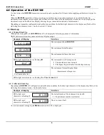
5.2 Calibration of the EX-5100 

Calibration is the process of setting the instrument up to read accurately when exposed to a target gas.  The Zero function sets 
the clean air reference point and the Span function sets the sensitivity of the instrument. 

Initial Calibration: 

Wait 24 hours after initially supplying power to the 

EX

-

5100 

sensor/transmitter (S/T) before initial calibration.  The S/T has 

been precalibrated at the factory, and initial field calibration should result in only fine tuning to circuit, as well as a way to 
check that installation is successful.  It is not necessary to open the enclosure to make adjustment; the span and zero 
potentiometers are operated with magnets from outside the enclosure.  Do Not open the S/T unless the area is de-classified. 

Calibration Zero and Span functions are two separate procedures.  They operate independently of each other.  It is 
recommended that the Zero procedure be done prior to the Span procedure.  

ENMET

 recommends at least quarterly calibration 

of the 

EX-5100

 transmitters. 

Calibration equipment is available from 

ENMET

 to calibrate the 

EX

-

5100 

sensor/transmitter.  A calibration adapter will have a 

fitting for the gas cylinder on one side and a cover to go over the sensor housing on the other. 

Generally, a cylinder of 20.9% Oxygen is used to provide a fresh air reference or Zero point for the calibration.  Another 
cylinder is used to provide the Span reference point for calibration.  Depending on the instrument calibration, the Span gas may 
be the same gas that the instrument is calibrated to display, or it may be another gas, which 

ENMET

 has found to have a similar 

response. 


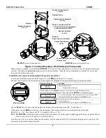
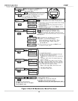
Figure 4: Calibration Adapter EX-5100 Sensor/Transmitter 

S

e

le

c

t

M

e

n

u

Select 

Menu 

Fitting to 
calibration cover 

Regulator 

Gas Cylinder 

Calibration Cover  
p/n 03620-015 

Summary of Contents for EX-5100

Page 1: ...ENMET PO Box 979 Ann Arbor MI 48106 0979 www enmet com Manual part number 80003 096 MCN 416 04 03 09 EX 5100 COMBUSTIBLE Manual...

Page 2: ...gs 13 5 4 Sensor Replacement 13 6 0 REPLACEMENT PART NUMBERS 14 7 0 WARRANTY 14 List of Figures and Tables FIGURE 1 EX 5100 FEATURES 2 FIGURE 2 EX 5100 MOUNTING DIMENSIONS 3 FIGURE 3 TERMINAL POSITION...

Page 3: ...spection and after you have received written acknowledgment of the damage from the carrier contact ENMET Customer Service for return authorization and further instructions Have your Purchase Order and...

Page 4: ...instrument maintenance functions The switch locations are indicated by MENU and SELECT A magnetic field pulse is applied by momentarily putting the end of the magnet in proximity to the switch and the...

Page 5: ...tters Take into consideration environmental factors when deciding on S T location Avoid locations where the S T may be damaged by liquid immersion excessive heat or other know hazards Also take precau...

Page 6: ...e supplied J8 plug then attach to the J8 terminal See Figure 3 for locations J4 PLUG TERMINAL TO CONTROLLER WIRING Position Function 1 24 VDC power 2 GND 3 4 20 mA out 4 RS 485 D 5 RS 485 D Contact EN...

Page 7: ...l Display Mode If intended function Tap the magnet over SELECT switch Tap the magnet over the MENU switch to advance to the Zero procedure For adjusting Zero If intended function Tap the magnet over S...

Page 8: ...NOTE Software revision may cause variations of display output Example of Display Function The instrument Model EX 5100 The instrument Serial Number The instrument Software Revision IF the right most c...

Page 9: ...lay indicates Alarm 1 Set point Tap the magnet over the MENU button Display indicates Alarm 2 Set point Tap the magnet over the MENU button No Function for the SELECT button in this mode Display indic...

Page 10: ...asurement of target gas Hold the magnet over MENU switch for 2 5 seconds to enter the Maintenance Menu The Power Fault LED will flash Green Red to indicate the EX 5100 is in Maintenance Mode To exit t...

Page 11: ...nd Span functions are two separate procedures They operate independently of each other It is recommended that the Zero procedure be done prior to the Span procedure ENMET recommends at least quarterly...

Page 12: ...ne Calibration coefficients relative to Methane have been generated for over 30 different combustible hydrocarbons and solvents A partial list of these gases and vapors are listed in Table 3 Non Stand...

Page 13: ...ociated calibration gas cylinder to the regulator and calibration cover See to Figure 3 4 Open the valve to apply the calibration gas to the sensor 5 Watch for the signal level to stabilize Refer to T...

Page 14: ...the magnet over the SELECT switch The MENU switch changes digit indicated by underscore cursor The SELECT switch locks underscored digit and moves to next digit See Section 5 2 2 SELECT mA Span MENU S...

Page 15: ...see Figure 5 for a detailed maintenance menu flow chart Example of Display Function Normal Display Mode Measurement of target gas Hold the magnet over the MENU switch for 2 4 seconds to enter the Mai...

Page 16: ...means of transportation is requested during the warranty period the customer is responsible for the difference between the most economical means and the expedient mode ENMET shall not be liable for an...

Page 17: ...ult in processing delays ENMET charges a one hour minimum billing for all approved repairs with additional time billed to the closest tenth of an hour All instruments sent to ENMET are subject to a mi...

Page 18: ...OD Check one K VISA MasterCard______________________ ________ ________ Card number Expiration Card Code K American Express______________________ ________ ________ Card number Expiration Card Code Name...

Reviews: