background image

WARRANTY REGISTRATION for England’s Stove Works 


Purchased by (Name) ______________________________________________ 


Address _________________________________________________________ 


City ________________________  State __________  Zip _________________ 


Telephone _______________________________________________________ 


Email Address ___________________________________________________ 


DEALER INFORMATION 


Purchased From (Dealer) ___________________________________________ 


Address _________________________________________________________ 


City ________________________  State __________  Zip _________________ 


UNIT INFORMATION 

(Please be sure to refer to sticker on back of manual or box to complete this section) 


Model Number _____________________  Purchase Date  _________________ 
 
Purchase Price  ____________________ 
 
Serial Number _____________________  Mfg. Date ______________________ 


How did you first hear about our product? (please check one) 

___ Word of Mouth 


___ Burn Trailer Demonstration 


___ Internet 

Other:  ____________________________________________________ 


Where did you receive information about our product? (please check one) 

___ Rec’d. info. via phone  ___ Dealer (Name of dealer):  ______________________ 
___ Internet       Other:  _________________________________________________ 


IMPORTANT NOTICE 

THIS REGISTRATION INFORMATION MUST BE ON FILE FOR THIS WARRANTY TO BE VALID. 

PLEASE MAIL THIS INFORMATION WITHIN THIRTY (30) DAYS FROM THE DATE OF PURCHASE. 


Mail To: 

England’s Stove Works, Inc. 

Technical Support Department 

P.O. Box 206 

Monroe, VA 24574 

Or, Fax To: 

(434) 929-4810 – 24 hours a day 


Or, now available – Go online to complete your Warranty Registration! 

Visit 

www.englanderstoves.com

 if you prefer to register online. 


25

Summary of Contents for 25-PI

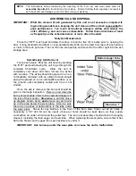
Page 1: ... any heating appliance Refer to this owner s manual for all clearances to combustible materials WARNING USE OF OUTSIDE AIR IS MANDATORY WITH THIS UNIT DO NOT OPERATE UNIT WITH HOPPER OPEN LID MUST BE SHUT AND TIGHTLY SECURED DO NOT OPERATE WITH DOOR OPEN SAFETY NOTICE FAILURE TO FOLLOW THESE INSTRUCTIONS COULD RESULT IN PROPERTY DAMAGE BODILY INJURY OR EVEN DEATH FOR YOUR SAFETY AND PROTECTION FOL...

Page 2: ...guide on our web site we have always tried to help our customers stay heat ready especially when oil and electricity prices continue to skyrocket Please look at our vast Help section on our web site and call our Technical Support department at 800 245 6489 if you need any help with your unit We are nearly always able to help walk you through any repairs problems or questions you may have PLEASE NO...

Page 3: ... that leads from this room to the rest of your home IN THE EVENT OF SMOKE BACK 1 If you see smoke coming out of your unit into the room due to a power failure DO NOT OPEN THE HOPPER OR DOOR TO YOUR UNIT Remain calm Open the nearest outside door and windows and wait for all signs of smoke to clear at least one hour although the smoke should dissipate quickly once the door and windows are opened Whe...

Page 4: ...Vent pipe and fasten each joint of the pipe with at least three screws 8 Outside combustion air is mandatory for these units to work properly Make this connection using a 1 7 8 I D metal pipe steel aluminum or copper and coupler Be sure to secure the pipe to the unit with a clamp or aluminum tape The outside end should be covered screened to prevent any foreign matter from entering the system Try ...

Page 5: ... Wax impregnated wood chips cardboard cubes or firestarter chips designed for pellet stoves see section on Manually Starting Unit Follow any manufacturer s directions for these products and NEVER place any firestarter on any hot surface or hot coals Never apply any firestarter products of any kind to a hot surface or hot coals UNIT PREPARATION 1 Attach the spring handle to the door by turning it c...

Page 6: ...nical Support 800 245 6489 www englanderstoves com Notes on termination of Pellet Vent Pipe see also FLUE SYSTEM section of manual 1 Not less than three 3 feet above any forced air inlet located within ten 10 feet 2 Not less than four 4 feet below four 4 feet horizontally from or one 1 foot above any door window or gravity air inlet into any building 3 Not less than two 2 feet from an adjacent bui...

Page 7: ... the dwelling The air intake pipe is located on the bottom center of the rear of the unit and measures 1 inside diameter I D The connection can be made with a metal 1 7 8 I D coupler and pipe see Important Information section of manual and should exit through the back wall of the fireplace or through a clean out door if available that leads directly outside of the dwelling external fireplace only ...

Page 8: ...the exhaust blower with high temperature silicone and a hose clamp It is recommended that a clean out tee Part AC 3067 is installed between the vent adapter and the five feet 5 of pellet flex pipe Part PU 3060F or pellet vent rated flex liner Route the open end of the flex pipe through the throat of the fireplace or if relining the flue with flex liner drop the liner through the top of the flue an...

Page 9: ...ill be required to use floor protection The unit requires eighteen inches 18 of protection in front of the firebox If you do not have enough space it can be achieved with a UL approved floor protector or equal and should be large enough to provide a minimum of six inches 6 on both sides of the stove Wall Protection From the sides of this stove only six inches 6 of clearance is required to paneling...

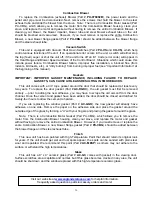
Page 10: ...means the unit failed to start normally After this code is received and you are sure the unit is working properly fill the hopper with wood pellets Do not allow any part of the bag or any foreign material in the hopper as this may jam the augers Ensure that all pellet matter is cleared from the hopper lid gasket make sure the hopper lid and the door of the unit are securely closed and press the ON...

Page 11: ...e the Shut Down procedure open the closest outside door and a window to eliminate the home s natural draft BEFORE opening the stove s door or hopper lid This will allow any smoke to exit through the exhaust hook up instead of spilling into the home SHUT DOWN PROCEDURE WARNING NEVER SHUT DOWN THIS UNIT BY UNPLUGGING IT FROM THE POWER SOURCE Refer to the following instructions Press the OFF touch pa...

Page 12: ...highly recommend the use of a surge protector with your unit as power surges and failures can affect the operation of any electrical appliance We do not recommend leaving home with the stove on the higher heat ranges it is recommended that the stove be left on the lower heat ranges Heat Range setting 1 or 2 NOTE Remember 1 It is very important for the unit to be vented properly see instructions on...

Page 13: ...by pressing the OFF pad and allowing the unit to go through the complete Shut Down cycle Allow the unit to completely cool down and then remove the ashes with a scoop The ashes should be placed in a non combustible container with an airtight lid and should always be placed on a non combustible surface or on the ground until completely cooled and free of hot cinders Once the ash is removed the burn...

Page 14: ...he feed tube and sand out any residue not removed from scraping alone Clearing this carbon residue from the feed tube is essential for proper operation of the feed auger which is designed to float freely in the feed tube allowing smooth fuel flow a lesser possibility of a jam and a quieter unit Annual Cleaning The stove and the flue system should be given a complete cleaning at the end of the heat...

Page 15: ...de from the locking collar There are two motor assemblies on the unit and both rest on a shelf when not in operation When replacing a motor the assembly should always be placed to rest on this shelf prior to starting the unit Auger Bearings and Auger Shafts The auger bearings Part PU UCF204 12 are a sealed unit and do not require lubrication To replace the Top Auger all the fuel must be removed fr...

Page 16: ... that should be replaced at least every two years To replace the door gasket Part AC DGKC the old gasket must first be removed entirely prior to adding the new adhesive you may have to scrape the old cement from the door channel Once the cement and gasket have been added the door should be closed and latched for twenty four hours to allow the cement to harden If you are replacing the window gasket...

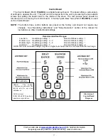
Page 17: ...ation section of the manual for instructions on other Control Board settings Illustration 3 Control Board Diagram CAUTION NOTE The bottom 3 buttons are pre set at the factory and do not need adjustment Call Service at 800 245 6489 if you have questions or problems Recommended Heat Ranges Low Burn Heat Range setting 1 Room Air Blower setting 1 Medium Low Heat Range setting 2 3 Room Air Blower setti...

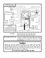
Page 18: ...er fired This condition could cause a house or chimney fire Do not operate your unit too hot or over firing may result Caution Should you see any evidence of smoke in the hopper smoke back immediately close and latch the hopper lid and door to the unit Open the nearest windows and door to the outside then press the OFF button and let the unit cool for at least 3 hours Do not open the door or hoppe...

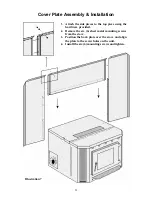
Page 19: ...ply matched to the proper edge and pressed onto the stove the back plate trim is assembled together with the two angle clips and then slipped over the back plate The top piece of this trim must be twisted out to go over the top lip of the cover plate After the screws in the angle clips are tightened the trim will stay in place NOTE For models manufactured 2001 and later there will be an extra piec...

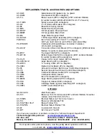
Page 20: ...gram PU UCF204 12 Auger Bearing 16 on diagram PU 2X570 Locking Collar 17 on diagram PU CB04 Digital Control Board 12 on diagram PU VS Vacuum Shut Down Switch see Control Board diagram CU VS Second Vacuum Switch see Control Board diagram PU CBG Combustion Blower Gasket 10 on diagram PU CMG Combustion Motor Gasket PU BPG Burn Pot Gasket 6 on diagram PU ABGN Auger Bearing Gasket 15 on diagram PU HLG ...

Page 21: ...Pellet Stove Exploded View Diagram Illustration 6 21 ...

Page 22: ... the top piece using the hardware provided 2 Remove the six 6 sheet metal mounting screws from the stove 3 Position the back plate over the stove and align the plate to the screw holes on the unit 4 Install the six 6 mounting screws and tighten Illustration 7 22 ...

Page 23: ...ide 4 Excessive ash 4 Remove baffles Clean unit 5 Low quality pellets 5 Use premium pellets 6 Blown fuse 6 AMP 1 Power surge 1 Replace fuse use surge protector 2 Exposed wire 2 Check for exposed or frayed wire and loose connections 3 Electric motor shorting or bound up 3 Check motors and blowers for obstructions or lock up 7 High pellet consumption 1 Low quality pellets 1 Use premium fuel 2 Board ...

Page 24: ...curs because of an accident improper handling improper installation improper operation abuse or unauthorized repair made or attempted to be made The manufacturer is not liable for indirect incidental or consequential damages in connection with the product including any cost or expense providing substitute equipment or service during periods of malfunction or nonuse All liability for any consequent...

Page 25: ...Date _________________ Purchase Price ____________________ Serial Number _____________________ Mfg Date ______________________ How did you first hear about our product please check one ___ Word of Mouth ___ Burn Trailer Demonstration ___ Internet Other ____________________________________________________ Where did you receive information about our product please check one ___ Rec d info via phone ...

Reviews: