England's Stove Works 17?VL Installation & Operation Manual Download Page 13

Page | 13  


INSTALLATION 


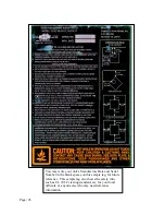
Approved Venting Method 3: Internal or External Masonry Chimney System 


Please Note: 

Installation diagrams are for reference purposes only and are not drawn to scale, nor meant to be used as plans for each individual 
installation.  Please follow all venting system requirements, maintain the required clearances to combustibles, and follow all local 
codes. 

Chimney


Connector


(Single


or


Double


Wall)


3.

0


ft.


2.

0


ft.


10


ft.


The


10

3

2


Rule:


The


chimney


system


must


terminate


3.0


ft.


above


the


point


where


its


centerline


passes


through


the


roof


AND


the


chimney


must


terminate


2.0


ft.


above


any


part


of


the


dwelling


within


a


10


ft.


radius


of


the


chimney.


18.

0


in.


Masonry


Thimble


with


proper


clearance


to


combustibles

Chimney


liner


cross

sectional


area


(Length


x


Width)


must


be


no


larger


than


twice


the


cross

sectional


area


of


the


flue


collar


(2


x


28.27


in

2


=


56.55


in

2

).


If


chimney


liner


is


larger


than


56.55


in

2

,


relining


with


a


5.5”


or


6.0”


liner


is


required


Ash


Cleanouts


must


have


an


airtight


seal


to


prevent


weak


draft.


Follow


the


rules


listed


above


concerning


maximum


permissible


flue


liner


size;


installing


this


unit


on


masonry


chimneys


exceeding


56.55


in

2


in


cross

sectional


area


will


result


in


decreased


draft


and


the


potential


for


poor


unit


performance.


Use


three


sheet


metal


screws


at


each


single


wall


chimney


connector


joint


(check


manufacturer’s


recommendations


when


double


wall


chimney


connector


is


used).


Drill


three


holes


in


the


flue


collar


of


the


unit


and


attach


the


chimney


connector


to


the


unit


using


sheet


metal


screws.


Avoid


numerous


elbows


and


excessive


horizontal


runs


as


both


will


lead


to


poor


draft


and


increased


creosote


accumulation.


Horizontal


runs


of


chimney


connector


must


never


exceed


4.0


ft.


and


the


overall


length


of


the


chimney


connector


must


not


exceed


8.0


ft.


A


tight


seal


at


the


thimble


is


crucial


for


proper


unit


performance


and


to


create


a


safe


installation.


Use


the


proper


adapter


designed


for


connecting


single


or


double


wall


chimney


connector


to


a


masonry


thimble.


Have


existing


masonry


chimneys


inspected


for


safety


and


proper


clearances


to


combustibles


before


putting


them


into


service;


a


qualified


chimney


sweep


can


perform


this


inspection.


External


masonry


chimneys


often


suffer


cold


downdrafts


and


poor


draft


performance


even


when


they


meet


the


cross

sectional


area


rules.


In


this


case,


a


6.0”


insulated


liner


may


be


necessary.


Summary of Contents for 17?VL

Page 1: ...g appliance SAFETY NOTICE Failure to follow these instructions can result in property damage bodily injury or even death For your safety and protection follow the installation instructions outlined in this manual Contact your local building or fire officials about restrictions and installation inspection requirements including permits in your area SAVE THESE INSTRUCTIONS Manufactured By England s ...

Page 2: ... with the outside combustion air hook up See the Installation section of this manual for details pertaining to mobile home installations Mobile home installation must be in accordance with the Manufactured Home and Safety Standard HUD CFR 3280 Part 24 CAUTION Keep children away Supervise children in the same room as this appliance Alert children and adults to the hazards of high temperatures Do NO...

Page 3: ...ide Air Hook Up 14 Floor Protection 15 R value Calculations 16 Operation Break In Fires 17 Lighting a Fire 17 Continuous Operation 18 Safety Notes 19 Maintenance Important Notes 20 Inspecting Gaskets 21 Glass and Gasket Replacement 22 Troubleshooting Guide Troubleshooting 23 Optional Accessories AC 16 Blower 24 Illustrated Parts Detail Parts List 24 Exploded Parts Diagram 25 Warranty Warranty Deta...

Page 4: ...er while remaining simple our stoves are designed to perform extremely efficiently helping deliver more heat from less fuel Please look at our vast Help section on our website and call our Technical Support Department at 800 245 6489 if you need any help with your unit We are nearly always able to walk you through any installation issues repairs problems or other questions that you may have Wishin...

Page 5: ...0 This unit was not tested for efficiency the efficiency shown is a default value normally attained by similar certified non catalytic wood Maximum burn time are heavily dependent on the type of wood burned in the stove as such these numbers may vary The maximum heating capacity of this unit can vary greatly based on climate construction style insulation and a myriad of other factors Use this info...

Page 6: ...eeping the entire chimney system inside the heated envelope of the home will ensure a strong easy to initiate draft in the chimney Although exterior chimney systems often function properly they are more likely to suffer from cold down drafts at start up or provide weak draft to the unit Also consider the cross sectional area of the chimney although existing masonry chimneys can often be used a lar...

Page 7: ...Connector to Rear Wall Unit to Rear Wall Unit to Corner Chimney Connector to Corner A B C D E F in mm in mm in mm in mm in mm in mm Single Wall Chimney Connector Unprotected Surface 12 304 8 19 5 495 3 12 304 8 10 254 0 7 177 8 15 381 0 Double Wall Chimney Connector Unprotected Surface 11 279 4 17 5 444 5 10 254 0 8 203 2 6 152 4 14 355 6 A B C D E F ...

Page 8: ...our installation meets local and national fire codes and if you re uncertain about how to safely install the stove we strongly recommend contacting a local NFI certified installer to perform the installation Venting Guidelines ALWAYS install vent pipe in strict adherence to the instructions and clearances included with your venting system DO NOT connect this wood stove to a chimney flue which also...

Page 9: ...amper with this unit Never use single wall or double chimney connector as a chimney system never pass either type of chimney connector through a combustible wall without carefully following the manufacturer s instructions and those listed in the following page on Wall Pass Throughs NEVER pass chimney connector through an attic floor closet or roof Only use 24 gauge MSG black single wall chimney co...

Page 10: ...Page 10 INSTALLATION Wall Pass Throughs In Canada the installation must conform to CAN CSA B365 when passing through combustible construction ...

Page 11: ...unit on prefabricated chimneys larger than 6 0 diameter will result in decreased draft and the potential for poor unit performance Follow all venting system manufacturer s installation requirements and required clearances Use three sheet metal screws at each single wall chimney connector joint check manufacturer s recommendations when double wall chimney connector is used Drill three holes in the ...

Page 12: ... chimney connector and chimney systems Installing this unit on prefabricated chimneys larger than 6 0 diameter will result in decreased draft and the potential for poor unit performance Follow all venting system manufacturer s installation requirements and required clearances Use three sheet metal screws at each single wall chimney connector joint check manufacturer s recommendations when double w...

Page 13: ...e flue liner size installing this unit on masonry chimneys exceeding 56 55 in2 in cross sectional area will result in decreased draft and the potential for poor unit performance Use three sheet metal screws at each single wall chimney connector joint check manufacturer s recommendations when double wall chimney connector is used Drill three holes in the flue collar of the unit and attach the chimn...

Page 14: ...his unit to outside combustion air Part No AC OAK5 If it is not feasible to use the AC OAK5 outside air hookup kit in your stove installation other materials may be used provided the following rules are followed o The pipe used for outside air hookup must be metal with a minimum thickness of 0209in 25 gauge mild steel or greater and an inside diameter of approximately 4 25in o Keep pipe runs short...

Page 15: ... unit A hearth rug is NOT an approved substitute for a proper hearth pad For the US The floor protector must extend at least 16 in from the front of the fuel opening 8 in from the sides of the door opening and 8 in from the rear of the unit For Canada The floor protector must extend at least 450 0 mm from the front of the fuel opening 200 0 mm from the sides of the door opening and 200 0 mm from t...

Page 16: ... alternate is acceptable EXAMPLE The specified floor protector should be thick material with a k factor of 0 84 The proposed alternate is 4 brick with a C factor of 1 25 over 1 8 mineral board with a k factor of 0 29 Step a Use formula above to convert specification to R value R 1 k x T 1 0 84 x 75 0 893 Step b Calculate R of proposed system 4 brick of C 1 25 therefore R brick 1 C 1 1 25 0 80 1 8 ...

Page 17: ...us Operation After the break in fires are complete this unit is ready for continuous operation When burning the stove continuously do not allow ash and coals to accumulate higher than 1 0 below the door opening Excessive coaling is often a result of burning wood at too high a burn rate and the coal bed should be allowed to burn down before reloading the stove with fresh wood Combustion air is deli...

Page 18: ...o only operate the room air blower after a fresh wood load has been allowed to burn for at least thirty 30 minutes Allowing a fresh load of wood to burn without the blower on ensures that the entire unit reaches proper operation temperatures and that the secondary combustion system is functioning properly Additionally follow the guidelines below for acceptable blower speeds When using the optional...

Page 19: ... latched loosely or open will allow excessive combustion air to reach the fire and will result in dangerously high unit temperatures High unit temperatures can damage the unit void the warranty or ignite creosote deposited in the chimney system by previous slow burning fires The natural draft that pulls air through this unit and allows the fire to burn uses the indoor air of the dwelling for combu...

Page 20: ...instructions Thoroughly clean the chimney system and the chimney connector system Since the chimney connector is generally exposed to high exhaust temperatures inspect it carefully for leaks and weak spots replace any questionable pieces In the case of straight through the roof chimney system be certain to remove the vermiculite baffle before pushing the chimney sweeping brush down into the firebo...

Page 21: ...kets should only be replaced with equivalent fiberglass gaskets purchased from England s Stove Works specifically for this unit Gaskets 1 Door This unit comes with a 5 8 rope gasket around the door that should be replaced at least every two years To replace the door gasket Part AC DGKNC the old gasket must first be removed entirely prior to adding the new adhesive you may have to scrape the old ce...

Page 22: ...cool 2 The build up on the glass will generally be light and water is normally sufficient to remove the deposits If stubborn soot persists use a cleaner made specifically for this purpose Do not scrape the glass or use abrasive cleaners 3 Rinse the glass with clean water and dry the glass before resuming normal operation Glass Replacement 1 Remove the door from the stove and rest it face down on a...

Page 23: ...rating Stove at Low Burn Rate 7 1 Operate the stove at higher burn rates to allow the air wash system to keep the glass clean 8 Wood Loaded Too Close to Glass 8 1 Never load wood so that it is touching the ceramic glass viewing window Coals build up in firebox 9 Operating Stove at High Burn Rates 9 1 Reduce combustion air control and allow coals to burn down before reloading Fire burns out of cont...

Page 24: ...ove is constructed with rear and top convection channels which allow the room air blower to pick up heat from the hottest regions of the stove and transfer it into the home The mounting screws for the blower are installed into the rear convection channel at the factory mounting the blower only requires a 5 16 open end or socket wrench to remove these screws and install the blower When routing the ...

Page 25: ...Page 25 ILLUSTRATED PARTS DIAGRAM 3 4 7 5 5 6 1 2 Cast Iron Door Assembly Welded Steel Stove Body 12 8 10 9 11 11 Window Retaining Screws 13 15 14 ...

Page 26: ...cture Date and Serial Number in the blank spaces on this sample tag for future reference This sample tag also shows the safety info such as UL ULC testing standard etc for your local officials or anyone else who may need reference information ...

Page 27: ...nty does not apply if damage occurs because of an accident improper handling improper installation improper operation abuse or unauthorized repair made or attempted to be made 3 The manufacturer is not liable for indirect incidental or consequential damages in connection with the product including any cost or expense providing substitute equipment or service during periods of malfunction or non us...

Page 28: ...was purchased or the factory at our option will perform the warranty service Other Rights This warranty gives you specific legal rights you may also have other rights which may vary from state to state Please Note This warranty is null and void if the attached warranty registration AND a copy of the sales receipt is not returned within thirty 30 days from the date of purchase Warranty is not trans...

Page 29: ...________________ VIII City_______________________ State________ Zip Code __________ Unit Information Refer to the sticker on the back of the manual or box to complete this section IX Model Number_____________________ Purchase Date _____________ X Purchase Price_____________________ XI Serial Number_____________________ Mfg Date_________________ Purchase Questions How did you first hear about our p...

Page 30: ...original date of purchase Use any of these three easy ways to send your warranty information in Mailing Address England s Stove Works Inc Technical Support Department P O Box 206 Monroe Virginia 24574 Fax Number 434 929 4810 Twenty four hours a day Online Registration Visit our warranty registration website at http www englanderstoves com warranty warranty html ...

Reviews: